Subaru Impreza 3 / Impreza WRX / Impreza WRX STI. Manual - part 723


  Index      Subaru     Subaru Impreza 3 / Impreza WRX / Impreza WRX STI - service repair manual 2008-2014 year


Search            


Content   ..  721  722  723  724   ..


Subaru Impreza 3 / Impreza WRX / Impreza WRX STI. Manual - part 723


SL-41

Remote Openers

SECURITY AND LOCKS

3. FUEL FILLER LID OPENER

5 door model
1) Remove the rear seat. <Ref. to SE-13, REMOV-

AL, Rear Seat.>

2) Remove  the  lower  inner  trim,  rear  quarter  trim

and floor mat on the driver’s side. Remove the clip

holding the cable.

3) Remove the opener lever and detach the cover.

4) Remove the bolts, then remove the pull handle

assembly.

5) Remove the cable from pull handle assembly.

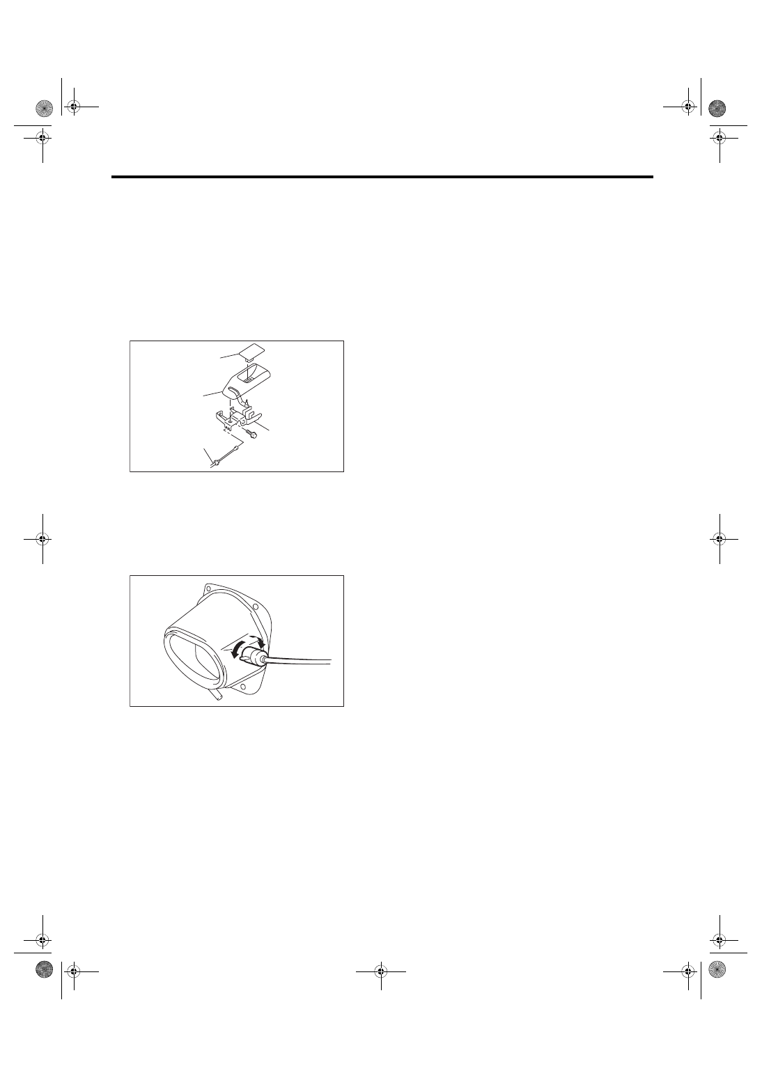
6) Rotate the fuel lock inside the quarter panel to

90° and remove. (Either right or left turn)

4 door model
Refer  to  the  trunk  lid  opener.  <Ref.  to  SL-40,

TRUNK LID OPENER, REMOVAL, Remote Open-

ers.>

B: INSTALLATION

Install each part in the reverse order of removal.

C: INSPECTION

Check if the front hood, trunk lid and fuel flap oper-

ate normally.

(1) Cover
(2) Pull handle ASSY
(3) Cable
(4) Opener lever

SL-01559

(2)

(1)

(3)

(4)

SL-00265

SL-42

Ignition Key Lock

SECURITY AND LOCKS

16.Ignition Key Lock

A: REPLACEMENT

1) Disconnect the ground cable from battery.

2) Remove  the  steering  column.  <Ref.  to  PS-16,

REMOVAL, Steering Column.>

3) Secure the steering column in a vise. Remove

the bolt with a drill.
CAUTION:

Do  not  apply  any  impact  to  the  set  bolt  by  a

chisel or punch.

4) Remove the ignition key lock.

5) Use  new  bolts.  Tighten  the  bolt  until  the  bolt

head is broken (bolt head wrenched off).

B: INSPECTION

1) Remove the instrument panel lower cover.

2) Remove the lower column cover.

3) Unfasten the fixing clip which secures harness,

and  then  disconnect  the  connector of the ignition

switch from body harness.

4) Turn the ignition key plate to each position and

check  the  resistance  between  ignition  connector

terminals.

5) Replace the ignition switch if the inspection re-

sult is not within the standard value.

SL-00024

SL-00876

Switch position

Terminal No.

Standard

LOCK

 — 

 — 

ACC

3 and 5

Less than 1 Ω

ON

3 and 1 and 4

3 and 5

Less than 1 Ω

ST

3 and 2

3 and 1 and 6

Less than 1 Ω

SL-00266

1

3

4

5

6

2

SL-43

Key Lock Cylinders

SECURITY AND LOCKS

17.Key Lock Cylinders

A: REPLACEMENT

1. FRONT DOOR

1) Raise the front door glass to the top position.

2) Remove the front door trim. <Ref. to EI-45, RE-

MOVAL, Door Trim.>

3) Remove the sealing cover. <Ref. to EB-21, RE-

MOVAL, Front Sealing Cover.>

4) Remove the rod clamp.

5) Remove the plug to the rear of the door panel.

6) Loosen TORX

®

 bolt (1).

7) Remove the key cylinder along with the handle

cover.

8) Remove the key cylinder from the cover, and re-

place the key cylinder.

2. GLOVE BOX LID

1) Remove the glove box damper.

2) Remove the stoppers and pull the glove box lid

assembly forward to remove.

3) Pull up the lock knob with the key cylinder in UN-

LOCK.

4) Insert the key while holding the condition of step

3), and pull out the key in LOCK status.

5) Remove  the  key  cylinder  from  lock  knob  while

pushing in the metal plate, and replace the key cyl-

inder.

(1) Latch connection rod
(2) Key cylinder
(3) Door outer handle cover

SL-00887

(1)

(1)

SL-00801

(1)

(2)

(3)

EI-01887

EI-01831

SL-01251

SL-01252

SL-01253

SL-44

Security Control Module

SECURITY AND LOCKS

18.Security Control Module

A: NOTE

The control of security system is carried out in body

integrated unit. Refer to the section on the body in-

tegrated unit for the work procedures.

• Removal: <Ref. to SL-48, REMOVAL, Body Inte-

grated Unit.>

• Installation:  <Ref.  to  SL-48,  INSTALLATION,

Body Integrated Unit.>


Content   ..  721  722  723  724   ..