Subaru Impreza 3 / Impreza WRX / Impreza WRX STI. Manual - part 722
SL-37
Rear Gate Latch and Actuator Assembly
SECURITY AND LOCKS
12.Rear Gate Latch and Actuator
Assembly
A: REMOVAL
1) Disconnect the ground cable from battery.
2) Remove the rear gate trim. <Ref. to EI-69, RE-
3) Remove the bolt.
4) Disconnect the harness connector, and remove
the rear gate latch and actuator assembly.
B: INSTALLATION
Install each part in the reverse order of removal.
Tightening torque:
Refer to “COMPONENT” of “General Descrip-
tion”. <Ref. to SL-3, REAR GATE LOCK AND
TRUNK LID, COMPONENT, General Descrip-
C: INSPECTION
1. REAR GATE LATCH
Check if the rear gate latch operates normally.
• If latch deformation, abnormal wear, or un-
smooth lock operation is observed, replace the rear
gate latch & actuator assembly.
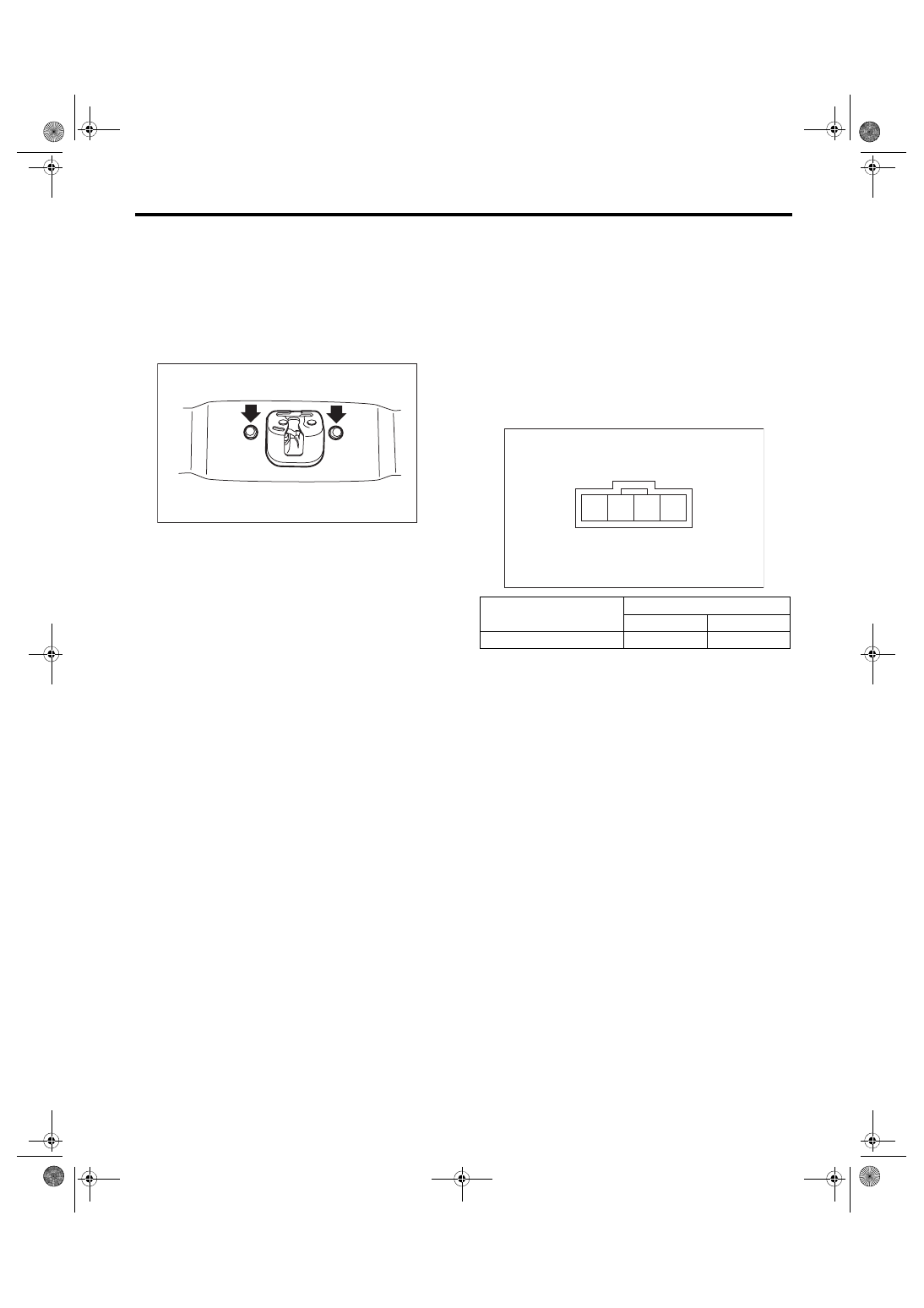
2. LOCK ACTUATOR
1) Disconnect the connector of rear gate latch and
actuator assembly.
2) Connect the battery to the lock actuator termi-
nals.
3) If the actuator does not operate normally, re-
place the rear gate latch & actuator assembly.
SL-00805
Actuator operation
Terminals
No. 1
No. 2
Lock → Unlock
+
–
SL-00745
4 3 2 1