Subaru Impreza 3 / Impreza WRX / Impreza WRX STI. Manual - part 719


  Index      Subaru     Subaru Impreza 3 / Impreza WRX / Impreza WRX STI - service repair manual 2008-2014 year


Search            


Content   ..  717  718  719  720   ..


Subaru Impreza 3 / Impreza WRX / Impreza WRX STI. Manual - part 719


SL-25

Keyless Entry System

SECURITY AND LOCKS

11.CHECK DOOR LOCK ACTUATOR AND CIRCUIT

For diagnostic procedures, refer to the INSPECTION of DOOR LOCK ACTUATOR & CIRCUIT of the Door

Lock Control System. <Ref. to SL-11, CHECK DOOR LOCK ACTUATOR AND CIRCUIT, INSPECTION,

Door Lock Control System.>

12.CHECK DOOR LOCK SWITCH

For operation procedure, refer to the door lock switch inspection of the door lock control system. <Ref. to SL-

9, CHECK DOOR LOCK SWITCH, INSPECTION, Door Lock Control System.>

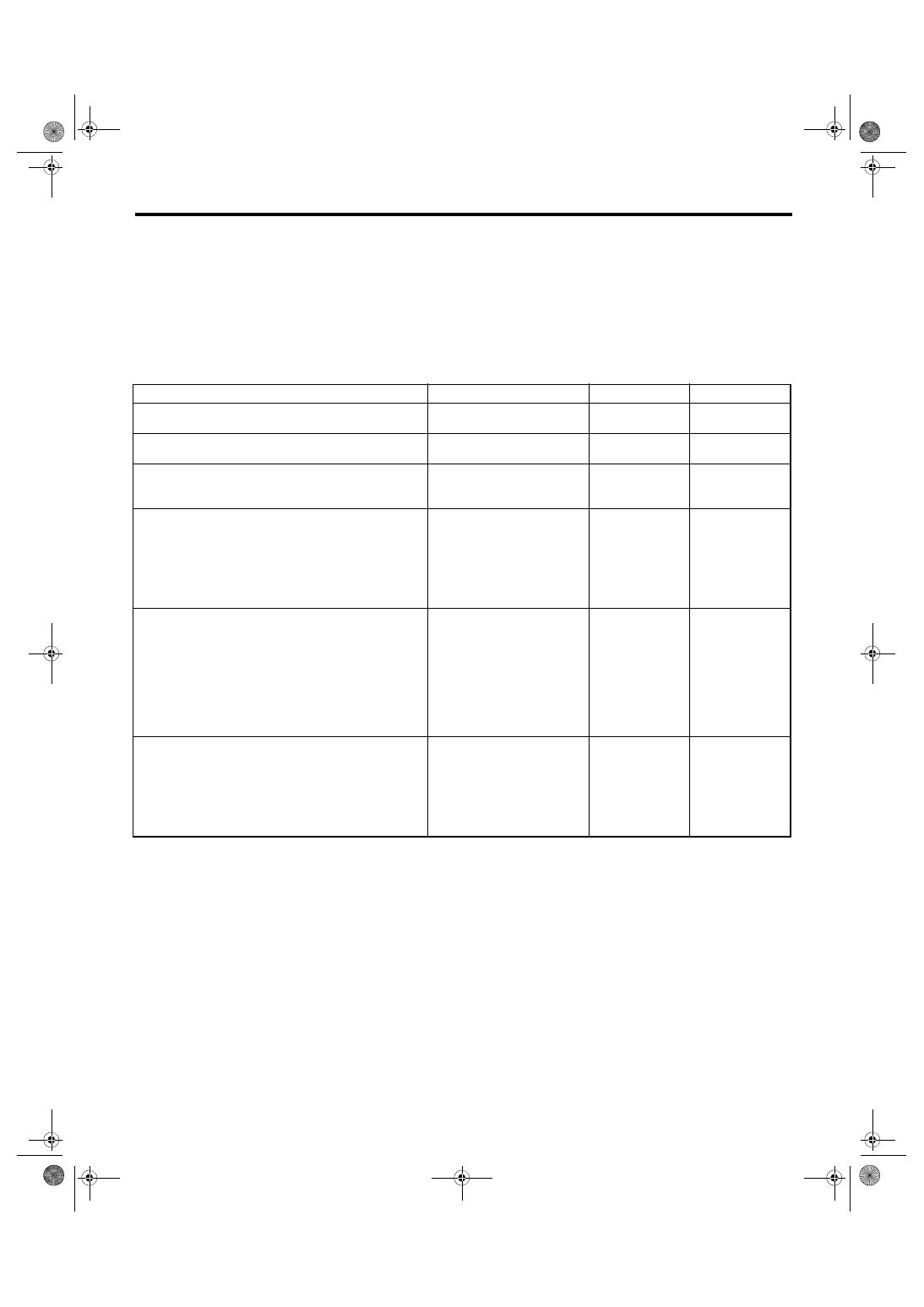
13.CHECK IGNITION SWITCH ILLUMINATION

Step

Check

Yes

No

1

CHECK IGNITION CIRCUIT.
Check the ignition circuit.

Is the circuit normal?

Go to step 

2.

Repair or replace.

2

CHECK DOOR SWITCH CIRCUIT.
Inspect door switch circuit.

Is the circuit normal?

Go to step 

3.

Repair or replace.

3

CHECK FUSE.
Remove and visually check fuse No. 14 (in the 
main fuse box).

Is the fuse blown out?

Replace the fuse 
with a new part.

Go to step 

4.

4

CHECK HARNESS.
1) Disconnect the ignition switch illumination 
harness connector.
2) Measure the voltage between harness con-
nector terminal and chassis ground.

Connector & terminal

(B224) No. 2 (+) — Chassis ground (–):

Is the voltage 10 V or more?

Go to step 

5.

Check the harness 
for open or short 
circuits between 
the ignition switch 
illumination and 
fuse.

5

CHECK IGNITION SWITCH ILLUMINATION 
CIRCUIT.
1) Disconnect the body integrated unit connec-
tor.
2) Check the harness between body inte-
grated unit connector and ignition switch illumi-
nation connector.

Connector & terminal

(B281) No. 23 — (B224) No. 1:

Is harness normal?

Go to step 

6.

Check the harness 
for open circuits 
and shorts 
between the body 
integrated unit and 
ignition switch illu-
mination.

6

CHECK IGNITION SWITCH ILLUMINATION 
BULB.
Apply battery voltage to the bulb.

Does the bulb illuminate?

Replace the body 
integrated unit. 
<Ref. to SL-48, 
Body Integrated 
Unit.>

Replace the igni-
tion switch illumi-
nation bulb. <Ref. 
to LI-37, 
REMOVAL, Igni-
tion Switch Illumi-
nation.>

SL-26

Security System

SECURITY AND LOCKS

4. Security System

A: WIRING DIAGRAM

Refer to “Security System” in WI section. <Ref. to WI-154, WIRING DIAGRAM, Security System.>

B: ELECTRICAL SPECIFICATION

1. BODY INTEGRATED UNIT

Refer to the Control Module I/O Signal of the LAN SYSTEM (DIAGNOSTICS) section. <Ref. to LAN(diag)-

10, ELECTRICAL SPECIFICATION, Control Module I/O Signal.>

C: INSPECTION

1. BASIC DIAGNOSTIC PROCEDURE

Step

Check

Yes

No

1

INITIAL CHECK.
Check keyless entry system.

Does the keyless entry system 
operate normally?

Go to step 

2.

Check keyless 
entry system. 
<Ref. to SL-15, 
INSPECTION, 
Keyless Entry Sys-
tem.>

2

CHECK SECURITY ON/OFF SETTING.
1) Press the LOCK button of the keyless trans-
mitter.
2) Check the security indicator light blinking 
patterns.

Is the security indicator light 
blinking patterns as follows? / 
When monitoring lag is set to 0 
seconds: flashes twice within 
0.5 seconds, in 2 second inter-
vals / When monitoring lag is 
set to 30 seconds: flashes 3 
times within 1 second, in 0.4 
second intervals.

Go to step 

5.

Go to step 

3.

3

CHANGE SETTING OF SECURITY SYSTEM.
Change the setting of security system to ON. 
<Ref. to SL-28, SECURITY SYSTEM ON/OFF 
SETTING, INSPECTION, Security System.>

Is setting change completed 
correctly?

Go to step 

4.

• Check the igni-
tion switch circuit. 
<Ref. to SL-29, 
CHECK IGNITION 
SWITCH CIRCUIT, 
INSPECTION, 
Security System.>
• Check the door 
lock switch circuit. 
<Ref. to SL-25, 
CHECK DOOR 
LOCK SWITCH, 
INSPECTION, 
Keyless Entry Sys-
tem.>

4

CHECK SETTING CHANGE OF SECURITY 
SYSTEM.
1) Remove the key from ignition switch, and 
then close all doors.
2) Press the LOCK button of the keyless trans-
mitter.
3) Check the security indicator light blinking 
patterns.

Is the security indicator light 
blinking patterns as follows? / 
When monitoring lag is set to 0 
seconds: flashes twice within 
0.5 seconds, in 2 second inter-
vals / When monitoring lag is 
set to 30 seconds: flashes 3 
times within 1 second, in 0.4 
second intervals.

Go to step 

5.

Refer to “SECU-
RITY INDICATOR” 
of “IMMOBILIZER 
(DIAGNOSTICS)”. 
<Ref. to IM(diag)-
11, CHECK 
SECURITY INDI-
CATOR LIGHT 
CIRCUIT, 
INSPECTION, 
Diagnostics Chart 
for Security Indica-
tor Light.>

SL-27

Security System

SECURITY AND LOCKS

NOTE:

If the horn sounds when the security is turned on (monitor condition) using the keyless transmitter, check the

function setting of the body integrated unit. As a cause, it is possible that the impact sensor present (ON) /

not present (OFF) setting is set to ON in the customization function though there is no impact sensor. <Ref.

to LAN(diag)-2, Basic Diagnostic Procedure.>

5

CHECK SECURITY SYSTEM OPERATION.
Press the LOCK button of keyless transmitter, 
and wait for 30 seconds.

Does the security indicator light 
blink twice within 0.5 seconds in 
2 second intervals?

Go to step 

6.

Replace the body 
integrated unit. 
<Ref. to SL-48, 
Body Integrated 
Unit.>

6

CHECK SECURITY ALARM OPERATION.
1) Unlock all doors using the door lock switch 
on driver’s door.
2) Open any door, trunk lid or rear gate.

Does the security alarm oper-
ate when opening any door, 
trunk lid, or rear gate?

Go to step 

7.

Check the door 
switch, trunk lid 
switch or rear gate 
latch switch. <Ref. 
to SL-19, CHECK 
DOOR SWITCH, 
INSPECTION, 
Keyless Entry Sys-
tem.>

7

CHECK SECURITY ALARM OPERATION.
Check the security alarm operation.

Do all security alarms operate? 
/ Horn sound / Hazard lights 
flash / Security indicator light 
illuminates

Go to step 

8.

• Check the horn. 
<Ref. to SL-28, 
CHECK HORN, 
INSPECTION, 
Security System.>
• Check the haz-
ard light. <Ref. to 
SL-22, CHECK 
HAZARD LIGHT 
OPERATION, 
INSPECTION, 
Keyless Entry Sys-
tem.>

8

CHECK SECURITY ALARM CANCEL OPER-
ATION.
Press any button of transmitter while the secu-
rity alarm is operating. Or turn the ignition 
switch to ON.

Do all security alarms stop? / 
Horn / Hazard lights

Go to step 

9.

Check the ignition 
switch circuit. 
<Ref. to SL-29, 
CHECK IGNITION 
SWITCH CIRCUIT, 
INSPECTION, 
Security System.>

9

CHECK SECURITY SYSTEM CONDITION 
MEMORY.
Check that the system functions properly even 
when the battery is not connected temporarily. 
<Ref. to SL-28, CHECK SECURITY SYSTEM 
CONDITION MEMORY, INSPECTION, Secu-
rity System.>

Does the system function prop-
erly when the battery is not con-
nected temporarily?

Go to step 

10.

Replace the body 
integrated unit. 
<Ref. to SL-48, 
Body Integrated 
Unit.>

10

CHECK IMPACT SENSOR (DEALER OP-
TION).
Check the sensibility of impact sensor. <Ref. to 
SL-45, CHECK IMPACT SENSOR, ADJUST-
MENT, Impact Sensor.>

Is the sensibility set properly?

Press the 
UNLOCK button of 
keyless transmit-
ter, and finish the 
diagnosis.

Adjust the sensitiv-
ity. <Ref. to SL-45, 
IMPACT SENSI-
TIVITY ADJUST-
MENT, 
ADJUSTMENT, 
Impact Sensor.>

Step

Check

Yes

No

SL-28

Security System

SECURITY AND LOCKS

2. CHECK SECURITY SYSTEM CONDITION MEMORY

1) Pull out the key from the ignition switch, or turn the ignition to OFF.

2) Close all the doors, trunk lid or rear gate.

3) Open the front hood.

4) Press the LOCK button of the keyless transmitter.
NOTE:

Wait until the security indicator light blinks twice within 0.5 seconds at 2 second intervals.

If the 30 second monitoring lag has been set, wait for 30 seconds.

5) Disconnect the ground cable from battery.

6) Connect the battery ground terminal.

7) Check that the security indicator light blinks twice within 0.5 seconds at 2 second intervals. When it does

not blink, replace the body integrated unit.

3. SECURITY SYSTEM ON/OFF SETTING

1) Close all doors, trunk lid or rear gate, and sit down on the driver seat. Press the UNLOCK button of the

keyless transmitter.

2) Turn the ignition switch to ON.

3) Push the centralized door lock switch down and open the driver’s side door at the same time, and hold in

this condition for 10 seconds. (Keep the central door unlock switch pressed down.)

4) If the security system is ON, it will turn OFF. If OFF, it will turn ON.

4. CHECK HORN

Setting

Horn activation

Meter display

ON → OFF

Twice

[AL_OF]

OFF → ON

Once

[AL_ON]

Step

Check

Yes

No

1

CHECK HORN OPERATION.
Check the horn sounds when the horn switch is 
pushed.

Does the horn sound?

Go to step 

2.

Check the horn cir-
cuit.

2

CHECK OUTPUT TO HORN RELAY.
1) Connect the Subaru Select Monitor Kit.
2) Turn the ignition switch to ON (engine OFF) 
and run the “PC application for Subaru Select 
Monitor”.
3) On «System Selection Menu» display, 
select {Integ. unit mode}.
4) Select {Function check}.
5) Select {Horn Output} and execute.

Does the horn sound?

Horn circuit is OK. Go to step 

3.

3

CHECK HORN RELAY CIRCUIT.
1) Turn the ignition switch to OFF.
2) Disconnect the harness connector of body 
integrated unit.
3) Disconnect the main fuse box harness con-
nector (B186).
4) Measure the resistance between harness 
connector terminals.

Connector & terminal

(B279) No. 29 — (B186) No. 1:

Is the resistance less than 10 

Ω?

Check body inte-
grated unit. <Ref. 
to LAN(diag)-2, 
Basic Diagnostic 
Procedure.>

Repair or replace 
the harness.


Content   ..  717  718  719  720   ..