Subaru Impreza 3 / Impreza WRX / Impreza WRX STI. Manual - part 695
GW-13
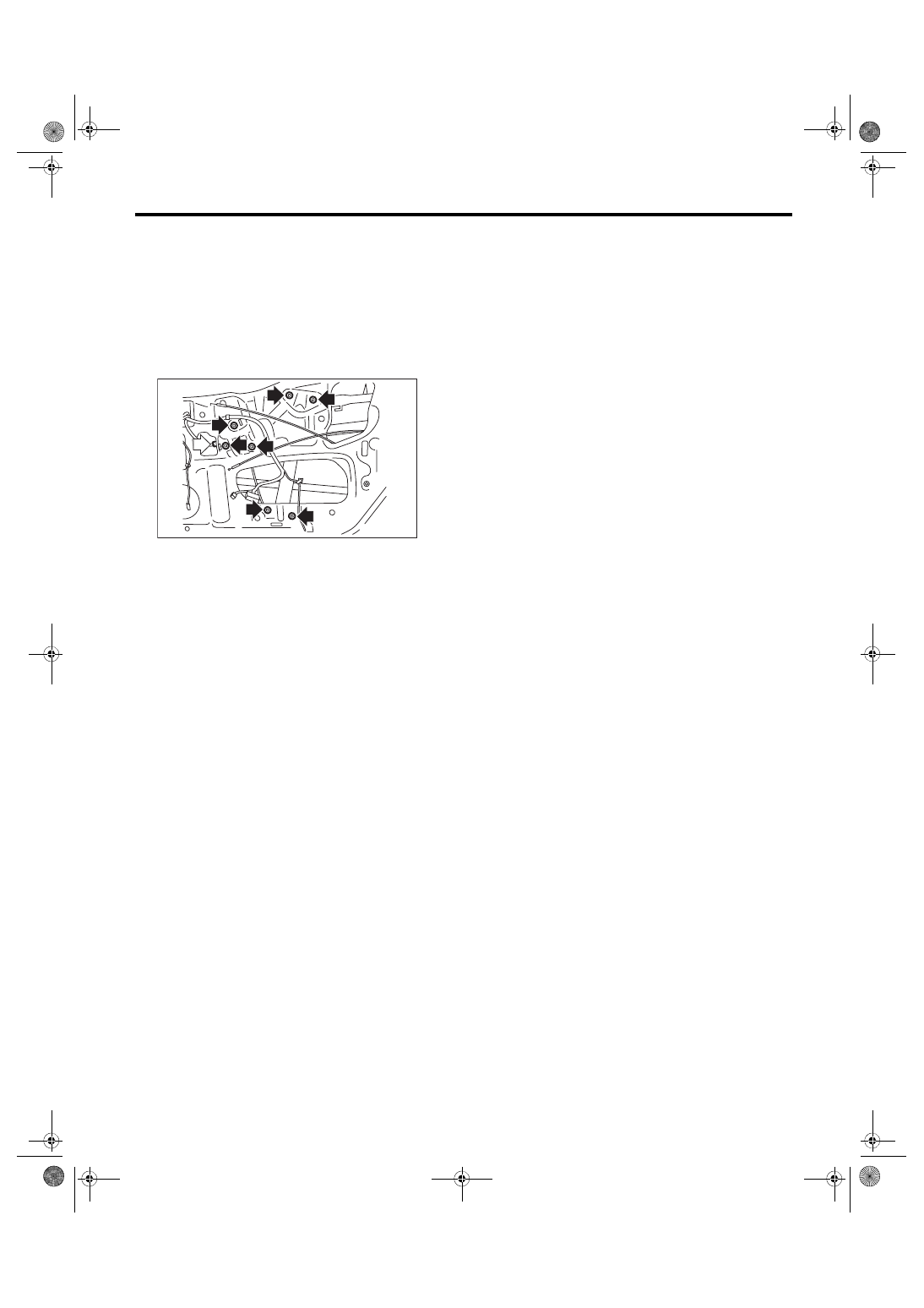
Front Regulator and Motor Assembly
GLASS/WINDOWS/MIRRORS
5. Front Regulator and Motor
Assembly
A: REMOVAL
1) Remove the front door glass. <Ref. to GW-12,
2) Disconnect the motor connector.
3) Remove the bolts, and then remove the front
regulator and motor assembly.
B: INSTALLATION
Install each part in the reverse order of removal.
Tightening torque:
Refer to “COMPONENT” of “General Descrip-
tion”. <Ref. to GW-4, FRONT DOOR GLASS,
COMPONENT, General Description.>
C: INSPECTION
1) Disconnect the motor connector.
2) Apply battery voltage between the motor con-
nector terminals and check the motor operation.
Check to ensure that the motor rotates in reverse
direction when the terminal to which battery voltage
is applied is changed.
3) If the inspection results in improper operation,
replace the front regulator and motor assembly.
GW-00697