Subaru Impreza 3 / Impreza WRX / Impreza WRX STI. Manual - part 694
GW-9
Power Window Control Switch
GLASS/WINDOWS/MIRRORS
3. Power Window Control
Switch
A: REMOVAL
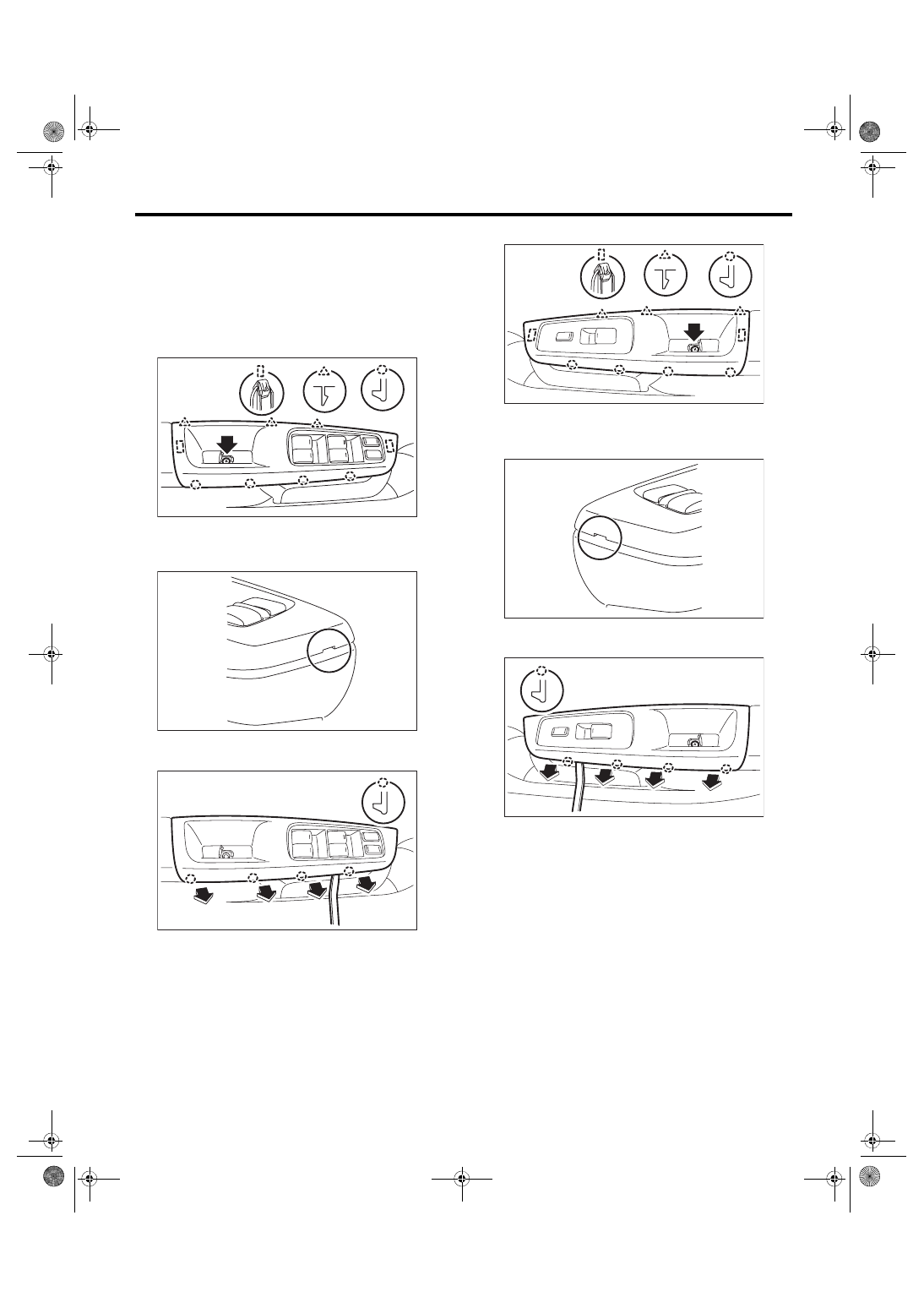
1. MAIN SWITCH
1) Disconnect the ground cable from battery.
2) Remove the power window switch panel.
(1) Open the cover and remove the screws.
(2) Lift up the tip of switch panel by using a plas-
tic remover.
(3) Disengage the end face tabs by using a
plastic remover.
(4) Remove the power window switch panel.
3) Disconnect the main switch connector.
4) Remove the screws to remove the power win-
dow main switch assembly.
2. SUB-SWITCH
1) Disconnect the ground cable from battery.
2) Remove the power window switch panel.
(1) Open the cover and remove the screws.
(2) Lift up the tip of switch panel by using a plas-
tic remover.
(3) Disengage the end face tabs by using a
plastic remover.
(4) Remove the power window switch panel.
3) Disconnect the power window sub-switch con-
nector.
4) Remove the screws to remove the power win-
dow sub-switch assembly.
B: INSTALLATION
CAUTION:
After installation of main switch, always per-
form the reset operation A (initial setting).
Failure to do so may cause the improper activa-
tion of auto-reverse operation for pinching haz-
ard prevention. <Ref. to GW-8, RESET
OPERATION A, INSPECTION, Power Window
Install each part in the reverse order of removal.
EI-03082
GW-00668
GW-00936
GW-00972
GW-00637
GW-00938