Subaru Impreza 3 / Impreza WRX / Impreza WRX STI. Manual - part 686


  Index      Subaru     Subaru Impreza 3 / Impreza WRX / Impreza WRX STI - service repair manual 2008-2014 year


Search            


Content   ..  684  685  686  687   ..


Subaru Impreza 3 / Impreza WRX / Impreza WRX STI. Manual - part 686


ET-3

Audio System

ENTERTAINMENT

2. Audio System

A: WIRING DIAGRAM

1. AUDIO

Refer to “Audio System” in the wiring diagram. <Ref. to WI-113, WIRING DIAGRAM, Audio System.>

B: INSPECTION

C: NOTE

For procedure of each component in the audio system, refer to the respective sections.

• Audio unit: <Ref. to ET-6, Audio.>

• Front speaker: <Ref. to ET-7, Front Speaker.>

• Tweeter: <Ref. to ET-8, Tweeter.>

• Rear speaker: <Ref. to ET-9, Rear Speaker.>

• Antenna: <Ref. to ET-10, Antenna.>

• Steering satellite switch: <Ref. to ET-11, Steering Satellite Switch.>

• Steering switch: <Ref. to ET-13, Steering Switch.>

• AUX input terminal: <Ref. to ET-18, AUX Input Terminal.>

• Microphone: <Ref. to ET-19, Microphone.>
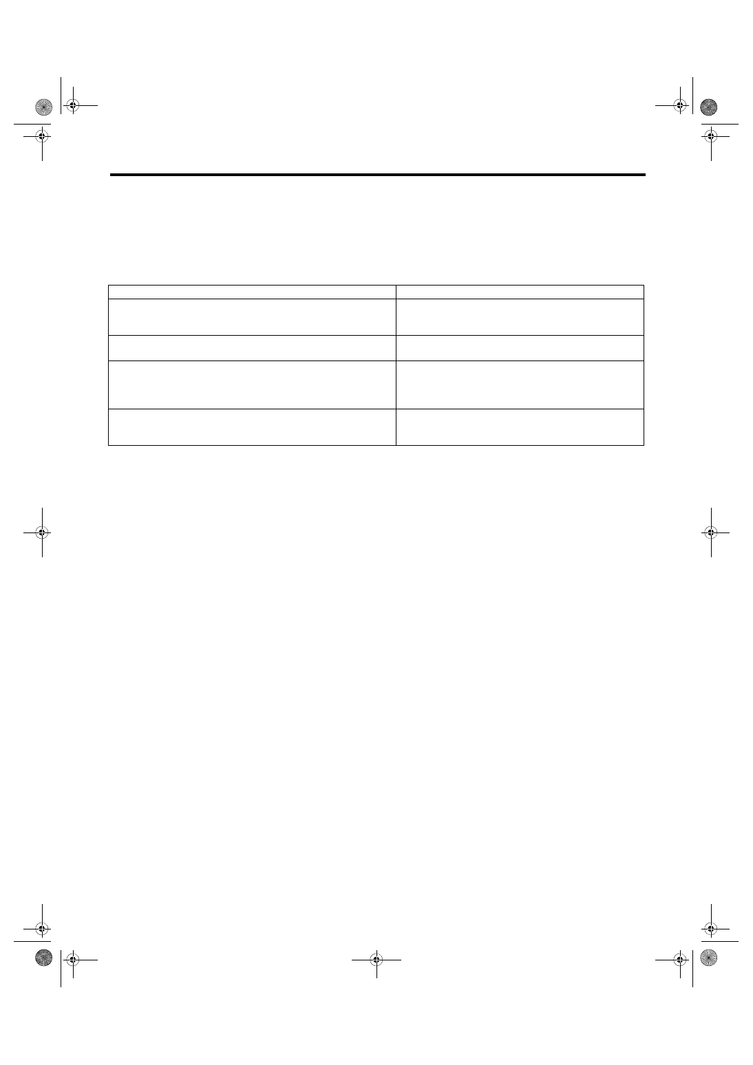
Symptom

Repair order

No power coming in. (No display and no sound from speakers)

1. Check the fuse and power supply for audio.
2. Check the audio ground.
3. Remove the audio for repair. 

A specific speaker does not operate.

1. Check the speaker.
2. Check the output circuit between audio and speaker.

Audio generates noise with engine is running.

1. Check the audio ground.
2. Check the generator.
3. Check the ignition coil.
4. Remove the audio for repair. 

Volume is low in AM and FM modes or interference noise occurs.

1. Check the antenna.
2. Check the audio ground.
3. Remove the audio for repair. 

ET-4

Navigation System

ENTERTAINMENT

3. Navigation System

A: WIRING DIAGRAM

Refer to “Navigation System” in the wiring diagram.

<Ref.  to  WI-123,  WIRING  DIAGRAM,  Navigation

System.>

B: INSPECTION

NOTE:

If no problems are found in “CHECK NAVIGATION

OPERATION”,  “CHECK  CONNECTION”  and

“CHECK  EACH  VEHICLE  SIGNAL”  as  described

below, check the navigation system circuit. <Ref. to

WI-123, WIRING DIAGRAM, Navigation System.>

1. CHECK THE OPERATION OF THE NAVI-

GATION

Start the engine and check that the opening screen

is displayed.

Standard: Opening screen is displayed.

OK: Normal.

NG: If the screen is not displayed, check whether

the map disc (SD CARD) is properly inserted. Or,

check the connection of the power supply connec-

tor on the reverse side of the navigation unit. If wire

connection  is  correct  or  has  got  repaired,  check

again that the opening screen is displayed.

If it is not displayed at this time, it indicates the nav-

igation unit trouble.

2. CHECK EACH CONNECTION

1) With  the  main  power  OFF,  press  and  hold  the

button (c) for 3 seconds or more while pressing the

buttons (a) and (b) simultaneously.

NOTE:

Pressing the button (a) for 3 seconds or more, or

turning the ignition switch from ACC OFF to ON po-

sition can exit the diagnostic mode.

2) Line Diag screen is displayed.

3) Check the connection status for each item listed

in “Connectivity Check” displayed on the left of the

screen.

OK: Each connection device is connected properly.

NG: No connection or abnormal connection is de-

tected.

4) Check the connection status of the connector. If

there  are  no  problems,  the  connection  device  or

unit could be faulty.

3. CHECK EACH VEHICLE SIGNAL

1) With  the  main  power  OFF,  press  and  hold  the

button (c) for 3 seconds or more while pressing the

buttons (a) and (b) simultaneously.

NOTE:

Pressing the button (a) for 3 seconds or more, or

turning the ignition switch from ACC OFF to ON po-

sition can exit the diagnostic mode.

2) Line Diag screen is displayed.

3) Check the connection status for each item listed

in “Vehicle Signal Check” displayed on the right of

the screen.

ET-00672

(a)

(b)

(c)

ET-00677

Camera  Setting

Audio  Check

Line Diag

OK

GPS

OK

MIC

NG

Rr_CAM

OK

AUX

OK

USB

OK

SAT

Connectivity Check

Vehicle Signal Check

ILL

+

SPD
PKB
REV

OFF

OFF

ON

OFF

ET-00672

(a)

(b)

(c)

ET-00677

Camera  Setting

Audio  Check

Line Diag

OK

GPS

OK

MIC

NG

Rr_CAM

OK

AUX

OK

USB

OK

SAT

Connectivity Check

Vehicle Signal Check

ILL

+

SPD
PKB
REV

OFF

OFF

ON

OFF

ET-5

Navigation System

ENTERTAINMENT

• Check illumination
NOTE:

Before starting inspections, turn the ignition switch

to ON.

1) Turn the lighting switch to level 1.

Make sure that the bright switch is not turned ON at

this time.

2) Make sure that “ON” lights in ILL+ and then the

screen becomes dim.

ON: Normal.

OFF: Abnormal. Check the signal line connector. If

there are no problems, the unit could be faulty.
• Check speed sensor
NOTE:

• Before  starting  inspections,  check  the  safety

around the vehicle.

• Lift up the vehicle as necessary.

• When the diagnostic trouble code is input in the

VDCCM, perform the Clear Memory operation.

1) Drive the vehicle at 9 km/h (6 mph) or more.

2) Check that “ON” is displayed in SPD.

ON: Normal.

OFF: Vehicle speed is less than 7 km/h (4 mph), or

malfunction is detected in the signal line. Check the

signal line connector. If there are no problems, the

unit could be faulty.
• Check parking brake signal
1) Pull parking brake lever.

2) Check that “ON” is displayed in PKB.

ON: Normal.

OFF: Abnormal. Check the signal line connector. If

there are no problems, the unit could be faulty.
• Check back sensor
NOTE:

Before  starting  inspections,  check  the  safety

around the rear end of the vehicle and then turn the

ignition switch to ON.

1) Pull  the  parking  brake  and  depress  the  brake,

then put the gear in reverse.

2) Make sure that “ON” is displayed in REV.

ON: Normal.

OFF: Abnormal. Check the signal line connector. If

there are no problems, the unit could be faulty.

C: NOTE

For procedure of each component in the navigation

system, refer to the respective section.

• Navigation  unit:  <Ref.  to  ET-14,  Navigation

Body.>

• GPS antenna: <Ref. to ET-15, GPS Antenna.>

ET-6

Audio

ENTERTAINMENT

4. Audio

A: REMOVAL

1) Disconnect the ground cable from battery.

2) Remove the center panel. <Ref. to EI-52, CEN-

TER PANEL, REMOVAL, Center Console.>

3) Remove the screws, and partially pull the audio

out from center console.

4) Disconnect the harness connectors and antenna

feeder cord.

5) Remove the audio.

6) Remove the screws and detach the satellite ra-

dio unit.

B: INSTALLATION

Install each part in the reverse order of removal.

ET-00471

ET-00294


Content   ..  684  685  686  687   ..