Subaru Impreza 3 / Impreza WRX / Impreza WRX STI. Manual - part 685
 

  Index      Subaru     Subaru Impreza 3 / Impreza WRX / Impreza WRX STI - service repair manual 2008-2014 year


Search            


Content   ..  683  684  685  686   ..


Subaru Impreza 3 / Impreza WRX / Impreza WRX STI. Manual - part 685


WW-21

Rear Wiper Motor

WIPER AND WASHER SYSTEMS

10.Rear Wiper Motor

A: REMOVAL

1) Disconnect the ground cable from the battery.

2) Remove  the  rear  wiper  arm.  <Ref.  to  WW-20,

REMOVAL, Rear Wiper Arm.>

3) Remove the rear gate lower trim. <Ref. to EI-69,

REMOVAL, Rear Gate Trim.>

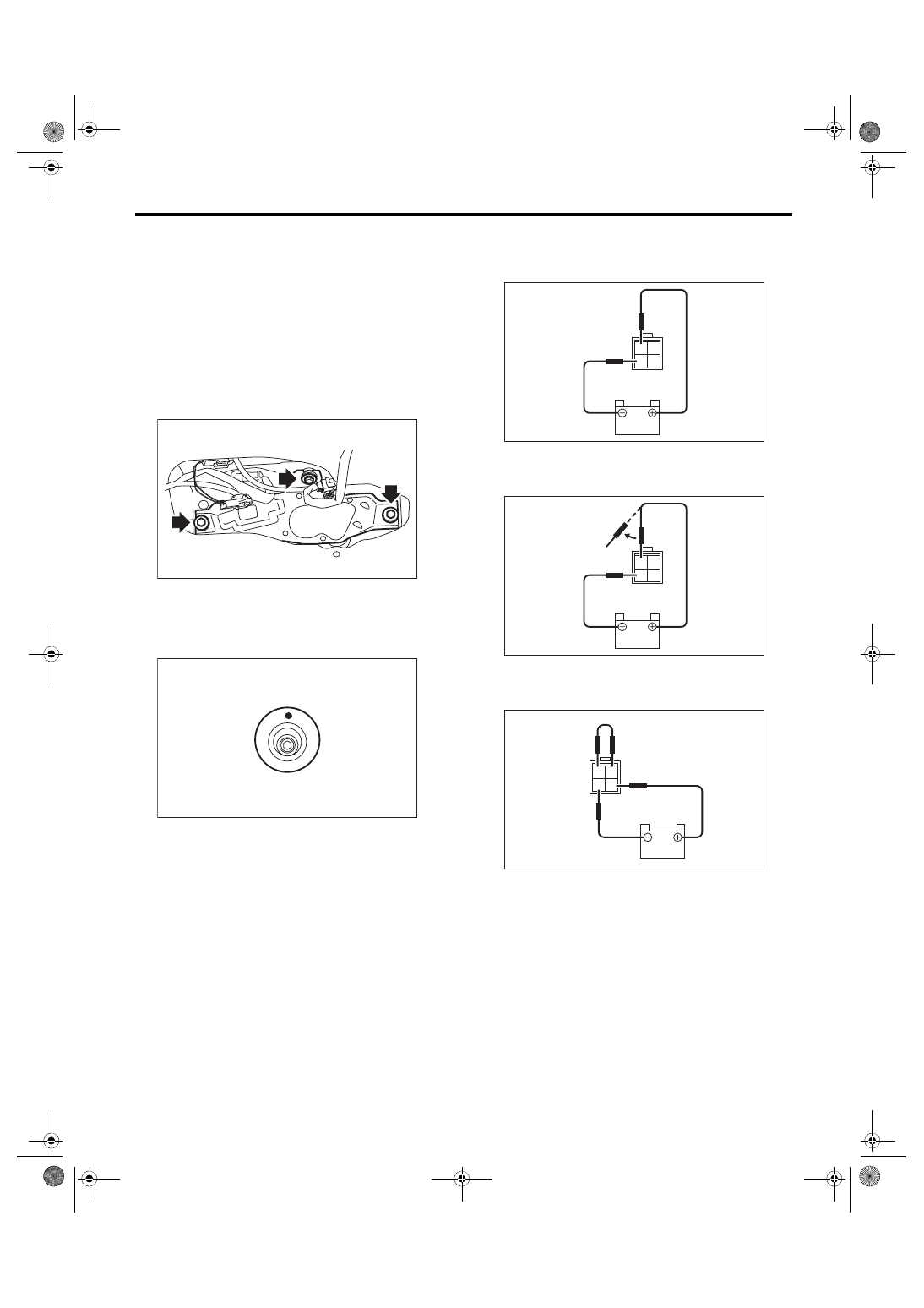
4) Disconnect the harness connector of wiper mo-

tor assembly.

5) Remove the bolt, and then remove the wiper mo-

tor assembly.

B: INSTALLATION

1) Install each part in the reverse order of removal.

2) Make sure that the pivot cap with the round mark

facing up, as shown in the figure.

Tightening torque:

Refer to “COMPONENT” of “General Descrip-

tion”. <Ref. to WW-3, REAR WIPER, COMPO-

NENT, General Description.>

C: INSPECTION

1) Connect the battery to the wiper motor connec-

tor and confirm that wiper motor operates.

2) Connect the battery to terminals of the connec-

tor, and remove the terminal connection with motor

rotating, and stop the wiper motor in mid-operation.

3) Connect the battery and confirm that the motor

stops at the automatic stop position after the motor

operates at low speed again.

WW-00492

WW-00545

WW-00508

2 1
4 3

WW-00509

2 1
4 3

WW-00510

2 1
4 3

WW-22

Rear Washer

WIPER AND WASHER SYSTEMS

11.Rear Washer

A: REMOVAL

1) Remove the high-mounted stop light. <Ref. to LI-

32, REMOVAL, High-mounted Stop Light.>

2) Remove the washer hose from the washer noz-

zle.

3) Push  the  claw  of  the  nozzle  from  the  reverse

side  of  roof  spoiler  with  a  flat  tip  screwdriver  or

equivalent, and remove the washer nozzle.

B: INSTALLATION

Install each part in the reverse order of removal.

C: INSPECTION

1. VISUAL CHECK

Check the following items, if a failure is found re-

place the parts.

• Make sure the nozzle and hose are not clogged.

• Make sure the hose is not bent.

2. SPRAY POSITION CHECK

1) Turn the wiper switch to OFF position.

2) While  the  vehicle  is  at  a  standstill,  make  sure

that the washer injection position is as shown in the

figure.

3) After check, if the spray position is largely differ-

ent from the position, replace with a new washer

nozzle.
Spray position:

A: 140 mm (5.5 in)

B: 70°

WW-00546

WW-00494

A

B

ENTERTAINMENT

ET

Page

1.

General Description  ...................................................................................2

2.

Audio System  .............................................................................................3

3.

Navigation System  .....................................................................................4

4.

Audio  ..........................................................................................................6

5.

Front Speaker  ............................................................................................7

6.

Tweeter  ......................................................................................................8

7.

Rear Speaker  .............................................................................................9

8.

Antenna ....................................................................................................10

9.

Steering Satellite Switch  ..........................................................................11

10.

Steering Switch  ........................................................................................13

11.

Navigation Body  .......................................................................................14

12.

GPS Antenna  ...........................................................................................15

13.

Front Accessory Power Supply Socket  ....................................................16

14.

Rear Accessory Power Supply Socket .....................................................17

15.

AUX Input Terminal ..................................................................................18

16.

Microphone  ..............................................................................................19

ET-2

General Description

ENTERTAINMENT

1. General Description

A: CAUTION

• Before disassembling or reassembling parts, always disconnect the battery ground cable from battery.

When replacing the audio, control module and other parts provided with memory functions, record the mem-

ory contents before disconnecting the battery ground cable. Otherwise, the memory is cleared.

• Reassemble the parts in the reverse order of disassembly procedure unless otherwise indicated.

• Adjust parts to the given specifications.

• Connect the connectors securely during reassembly.

• After reassembly, make sure that the functional parts operate normally.

B: PREPARATION TOOL

1. GENERAL TOOL

TOOL NAME

REMARKS

Circuit tester

Used for measuring resistance and voltage.


Content   ..  683  684  685  686   ..