Subaru Impreza 3 / Impreza WRX / Impreza WRX STI. Manual - part 671


  Index      Subaru     Subaru Impreza 3 / Impreza WRX / Impreza WRX STI - service repair manual 2008-2014 year


Search            


Content   ..  669  670  671  672   ..


Subaru Impreza 3 / Impreza WRX / Impreza WRX STI. Manual - part 671


LI-7

Turn Signal Light and Hazard Light System

LIGHTING SYSTEM

5. Turn Signal Light and Hazard 

Light System

A: WIRING DIAGRAM

Refer to “Turn Signal Light and Hazard Light Sys-

tem” in WI section. <Ref. to WI-103, WIRING DIA-

GRAM,  Turn  Signal  Light  and  Hazard  Light

System.>

B: INSPECTION

1. TURN SIGNAL SWITCH

Measure the resistance between turn signal switch

terminals. <Ref. to LI-11, INSPECTION, Combina-

tion Switch (Light).>

2. HAZARD SWITCH

1) Measure the resistance between hazard switch

terminals.

2) If the result of the inspection is not at the stan-

dard value, replace the hazard switch.

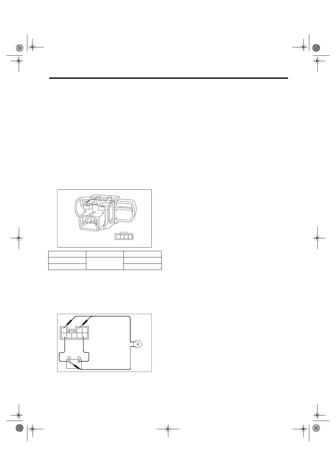
3. TURN SIGNAL AND HAZARD MODULE

1) Connect the battery and turn signal light bulb to

the module. The module is properly functioning if it

blinks when power is supplied to the circuit.

2) Replace the turn signal & hazard module if it is

found defective.

C: NOTE

For operation procedures of each component of the

turn signal and hazard light system, refer to the re-

spective sections.

• Rear combination light assembly: <Ref. to LI-25,

Rear Combination Light Assembly.>

• Side  turn  signal  light  assembly:  <Ref.  to  LI-24,

Side Turn Signal Light Assembly.>

• Front turn signal light bulb: <Ref. to LI-19, Front

Turn Signal Light Bulb.>

• Rear turn signal light bulb: <Ref. to LI-27, Rear

Turn Signal Light Bulb.>

• Combination switch (light): <Ref. to LI-11, Com-

bination Switch (Light).>

• Combination base switch: <Ref. to LI-14, Combi-

nation Base Switch Assembly.>

Switch position

Terminal No.

Specification

OFF

2 and 3

1 MΩ or more

ON

Less than 1 Ω

LI-00799

4 3 2 1

LI-00262

3

2 1

8 7 6 5 4

LI-8

Back-up Light System

LIGHTING SYSTEM

6. Back-up Light System

A: WIRING DIAGRAM

Refer  to  “Back-up  Light  System”  in  WI  section.

<Ref. to WI-95, WIRING DIAGRAM, Back-up Light

System.>

B: INSPECTION

1. BACK-UP LIGHT SWITCH

1) Measure  the  resistance  between  back-up  light

switch terminals.

2) Replace the back-up light switch if the inspection

result is not within the standard value.

C: NOTE

For operation procedures of each component of the

back-up light system, refer to the respective sec-

tion.

• Rear combination light assembly: <Ref. to LI-25,

Rear Combination Light Assembly.>

• Back-up light bulb: <Ref. to LI-30, Back-up Light

Bulb.>

Switch position

Terminal No.

Specification

When shift lever is 

set in reverse 

position

1 and 2

Less than 1 Ω

Other positions

1 MΩ or more

LI-00263

2 1

LI-9

Stop Light System

LIGHTING SYSTEM

7. Stop Light System

A: WIRING DIAGRAM

Refer to “Stop Light System” in WI section. <Ref. to

WI-96, WIRING DIAGRAM, Stop Light System.>

B: INSPECTION

1. STOP LIGHT SWITCH

1) Measure  the  resistance  between  stop  light

switch terminals.

• 5 door model

• 4 door model

2) Replace the stop light switch if the inspection re-

sult is not within the standard value.

C: NOTE

For operation procedures of each component of the

stop light system, refer to the respective section.

• Rear combination light assembly: <Ref. to LI-25,

Rear Combination Light Assembly.>

• Tail light/stop light bulb: <Ref. to LI-26, Tail/Stop

Light Bulb.>

• High-mounted  stop  light:  <Ref.  to  LI-32,  High-

mounted Stop Light.>

Switch position

Terminal No.

Specification

When brake pedal 

is depressed

5 door model:

1 and 2

4 door model:

3 and 4

Less than 1 Ω

When brake pedal 

is released

1 MΩ or more

3

4

1

2

LI-00840

3

4

1

2

LI-00841

LI-10

Room Light System

LIGHTING SYSTEM

8. Room Light System

A: WIRING DIAGRAM

Refer to “Interior Light System” in WI section. <Ref.

to WI-106, WIRING DIAGRAM, Interior Light Sys-

tem.>

B: INSPECTION

1. DOOR SWITCH

1) Measure the resistance between door switch ter-

minals.

2) Replace the door switch if the inspection result is

not within the standard value.

2. REAR GATE LATCH SWITCH

1) Measure the resistance between rear gate latch

switch terminals.

2) If the inspection result is not within the standard

value, replace the rear gate latch and actuator as-

sembly.

3. TRUNK LID LATCH SWITCH

1) Measure the resistance between trunk lid latch

switch terminals.

2) If the inspection result is not within the standard

value, replace the trunk lid latch and actuator as-

sembly.

C: NOTE

For operation procedures of each component of the

room light system, refer to the respective section.

• Spot map light: <Ref. to LI-33, Spot Map Light.>

• Room light: <Ref. to LI-34, Room Light.>

• Luggage  room  light:  <Ref.  to  LI-35,  Luggage

Room Light.>

• Trunk  room  light:  <Ref.  to  LI-36,  Trunk  Room

Light.>

• Door switch: <Ref. to LI-41, Door Switch.>

• Ignition switch illumination: <Ref. to LI-37, Igni-

tion Switch Illumination.>

Switch position

Terminal No.

Specification

When door is 

opened

1 and 3

Less than 1 Ω

When door is 

closed

1 MΩ or more

Switch position

Terminal No.

Standard value

When rear gate is 

opened

3 and 4

Less than 1 Ω

When rear gate is 

closed

1 MΩ or more

1

2

3

LI-00007

LI-00947

4 3 2 1

Switch position

Terminal No.

Standard value

When trunk lid is 

opened

1 and 3

Less than 1 Ω

When trunk lid is 

closed

1 MΩ or more

LI-00277

1

2

3


Content   ..  669  670  671  672   ..