Subaru Impreza 3 / Impreza WRX / Impreza WRX STI. Manual - part 670
 

  Index      Subaru     Subaru Impreza 3 / Impreza WRX / Impreza WRX STI - service repair manual 2008-2014 year


Search            


Content   ..  668  669  670  671   ..


Subaru Impreza 3 / Impreza WRX / Impreza WRX STI. Manual - part 670


LI-3

General Description

LIGHTING SYSTEM

C: PREPARATION TOOL

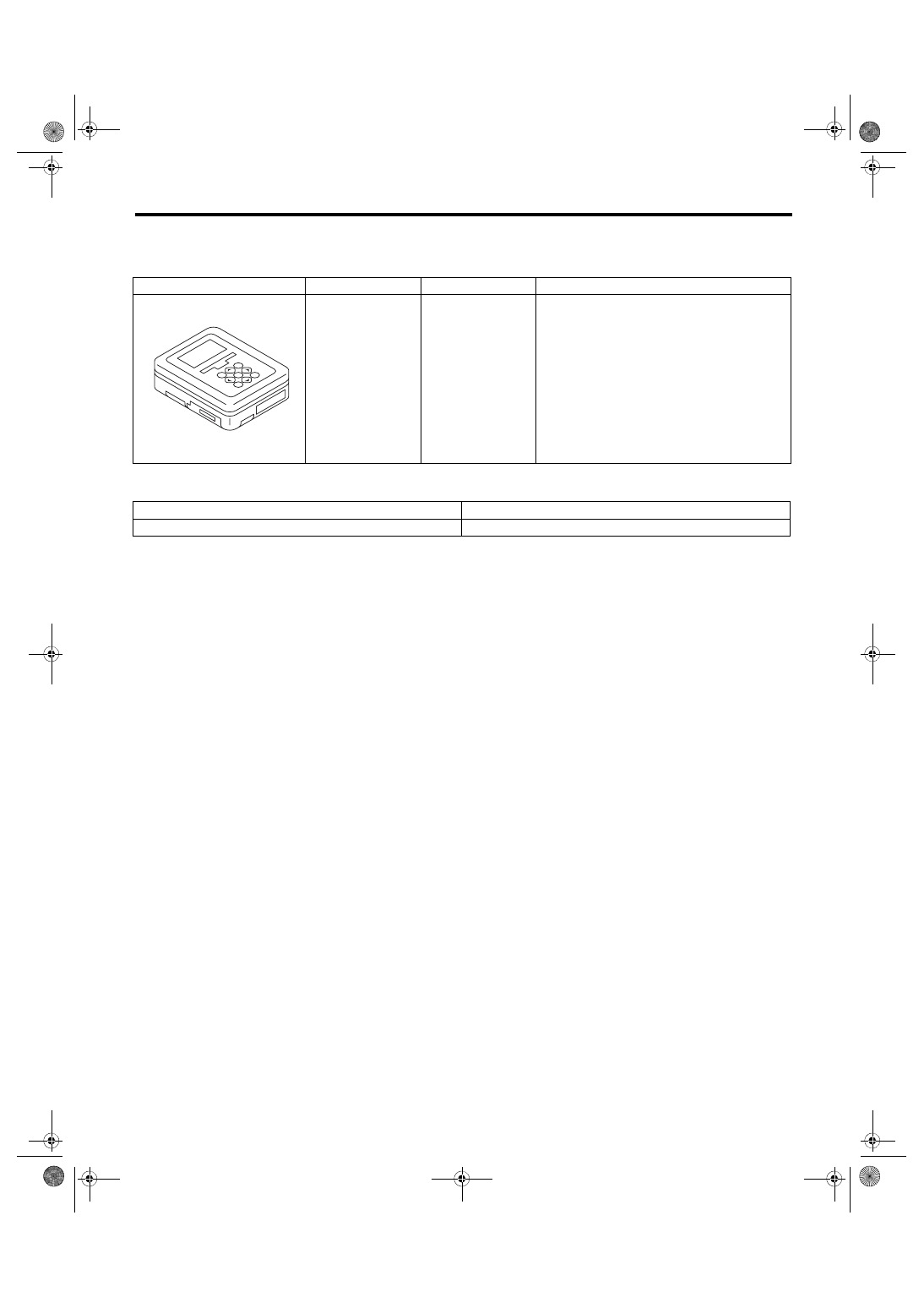
1. SPECIAL TOOL

2. GENERAL TOOL

ILLUSTRATION

TOOL NUMBER

DESCRIPTION

REMARKS

1B022XU0

SUBARU SELECT 
MONITOR III KIT

Used for troubleshooting the electrical system.

TOOL NAME

REMARKS

Circuit tester

Used for measuring resistance and voltage.

ST1B022XU0

LI-4

Headlight and Tail Light System

LIGHTING SYSTEM

2. Headlight and Tail Light Sys-

tem

A: WIRING DIAGRAM

1. HALOGEN TYPE HEADLIGHT

Refer to “Headlight System” in WI section. <Ref. to

WI-90, WIRING DIAGRAM, Headlight System.>

2. HID TYPE HEADLIGHT

Refer to “Headlight System” in WI section. <Ref. to

WI-90, WIRING DIAGRAM, Headlight System.>

3. CLEARANCE LIGHT AND ILLUMINA-

TION LIGHT

Refer  to  “Clearance  Light  and  Illumination  Light

System” in WI section. <Ref. to WI-98, WIRING DI-

AGRAM,  Clearance  Light  and  Illumination  Light

System.>

B: INSPECTION

1. LIGHTING SWITCH

Measure the resistance between lighting switch ter-

minals. <Ref. to LI-11, INSPECTION, Combination

Switch (Light).>

2. DIMMER AND PASSING SWITCH

Measure the resistance between dimmer & passing

switch  terminals.  <Ref.  to  LI-11,  INSPECTION,

Combination Switch (Light).>

3. HEADLIGHT RELAY

1) Connect  terminal  No.  4  to  the  battery  positive

terminal and the terminal No. 3 to the battery neg-

ative terminal, and check the resistance value be-

tween the headlight relay terminals.

2) Replace the headlight relay if the inspection re-

sult is not within the standard value.

4. TAIL AND ILLUMINATION RELAY

1) Connect  terminal  No.  4  to  the  battery  positive

terminal and terminal No. 3 to the battery ground

terminal, and check the resistance between tail and

illumination relay terminals.

2) If the result of the inspection is not at the stan-

dard value, replace the tail & illumination relay.

C: NOTE

For operation procedures of each component of the

headlight system, refer to the respective section.

• Headlight  Assembly:  <Ref.  to  LI-15,  Headlight

Assembly.>

• Headlight bulb: <Ref. to LI-17, Headlight Bulb.>

• Combination switch (light): <Ref. to LI-11, Com-

bination Switch (Light).>

• Combination base switch: <Ref. to LI-14, Combi-

nation Base Switch Assembly.>

• License plate light: <Ref. to LI-31, License Plate

Light.>

• Front side marker light bulb: <Ref. to LI-20, Front

Side Marker Light Bulb.>

• Rear combination light assembly: <Ref. to LI-25,

Rear Combination Light Assembly.>

• Rear finisher light assembly: <Ref. to LI-29, Rear

Finisher Light Assembly.>

• Tail light/stop light bulb: <Ref. to LI-26, Tail/Stop

Light Bulb.>

• Rear side marker light bulb: <Ref. to LI-28, Rear

Side Marker Light Bulb.>

Continuity

Terminal No.

Specification

Yes

1 and 2

Less than 1 Ω

No

1 MΩ or more

LI-00001

(1)

(2)

(1)

(4)

(2)

(3)

(3)

(4)

Continuity

Terminal No.

Specification

Yes

1 and 2

Less than 1 Ω

No

1 MΩ or more

LI-00001

(1)

(2)

(1)

(4)

(2)

(3)

(3)

(4)

LI-5

Day Time Running Light System

LIGHTING SYSTEM

3. Day Time Running Light System

A: WIRING DIAGRAM

Refer to “Headlight System” in WI section. <Ref. to WI-90, WIRING DIAGRAM, Headlight System.>

B: INSPECTION

1. DAYTIME RUNNING LIGHT MODULE CHECK

2. DAYTIME RUNNING LIGHT RELAY

1) Check the resistance between the daytime running relay terminals when connecting terminal No. 3 to the

battery positive terminal and terminal No. 5 to the battery ground terminal.

2) Replace the daytime running light relay if the inspection result is not within the standard value.

Step

Check

Yes

No

1

CHECK DTC.
1) Connect the Subaru Select Monitor.
2) Read the DTC of the integrated unit.

Is DTC displayed?

Perform the diag-
nosis according to 
DTC.

Go to step 

2.

2

CHECK INPUT SIGNAL.
1) Display the current data of the integrated 
unit.
2) Check the following input signals.

(1) Parking brake switch
(2) Shift position
(3) Light 2

Is the input signal normal?

Go to step 

3.

Check the defec-
tive part.

3

CHECK RELAY.
Check the daytime running light relay.

Is the relay OK?

Go to step 

4.

Replace the relay.

4

CHECK HARNESS.

Is the harness normal?

Replace the inte-
grated unit.

Repair the har-
ness.

LI-00829

(7)

(6)

(7)

(4)

(6)

(3)

(3)

(4)

(5)

(5)

Continuity

Terminal No.

Specification

Yes

7 and 6

Less than 1 Ω

No

1 MΩ or more

Yes

7 and 4

1 MΩ or more

No

Less than 1 Ω

LI-6

Front Fog Light System

LIGHTING SYSTEM

4. Front Fog Light System

A: WIRING DIAGRAM

Refer  to  “Front  Fog  Light  System”  in  WI  section.

<Ref.  to  WI-94,  WIRING  DIAGRAM,  Front  Fog

Light System.>

B: INSPECTION

1. FRONT FOG LIGHT SWITCH

Measure  the  resistance  between  front  fog  light

switch  terminals.  <Ref.  to  LI-11,  INSPECTION,

Combination Switch (Light).>

2. FRONT FOG LIGHT RELAY

1) Connect  terminal  No.  4  to  the  battery  positive

terminal and the terminal No. 3 to the battery neg-

ative terminal, and check the resistance value be-

tween the front fog light relay terminals.

2) If the result of the inspection is not at the stan-

dard value, replace the front fog light relay.

C: NOTE

For operation procedures of each component of the

front fog light system, refer to the respective sec-

tion.

• Front  fog  light  assembly:  <Ref.  to  LI-21,  Front

Fog Light Assembly.>

• Front  fog  light  bulb:  <Ref.  to  LI-23,  Front  Fog

Light Bulb.>

• Combination switch (light): <Ref. to LI-11, Com-

bination Switch (Light).>

• Combination base switch: <Ref. to LI-14, Combi-

nation Base Switch Assembly.>

Continuity

Terminal No.

Specification

Yes

1 and 2

Less than 1 Ω

No

1 MΩ or more

LI-00001

(1)

(2)

(1)

(4)

(2)

(3)

(3)

(4)


Content   ..  668  669  670  671   ..