Subaru Impreza 3 / Impreza WRX / Impreza WRX STI. Manual - part 611
 

  Index      Subaru     Subaru Impreza 3 / Impreza WRX / Impreza WRX STI - service repair manual 2008-2014 year


Search            


Content   ..  609  610  611  612   ..


Subaru Impreza 3 / Impreza WRX / Impreza WRX STI. Manual - part 611


AB-11

Airbag Connector

AIRBAG SYSTEM

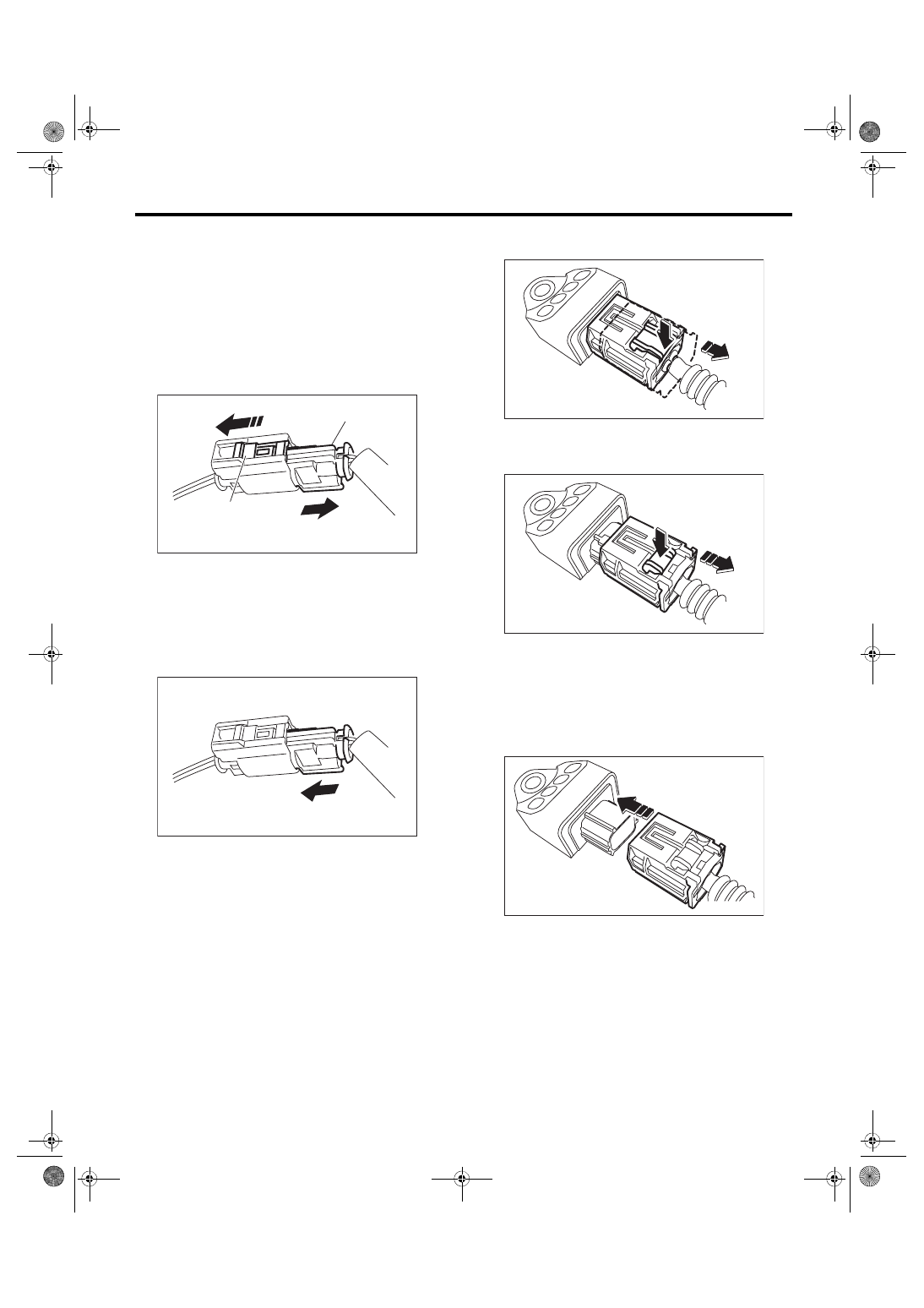
8. BUCKLE SWITCH RH

1) How to disconnect:
CAUTION:

When  pulling  the  slide  lock  or  disconnecting

connector, be sure to hold the connector, not

the harness.

(1) Move the slide lock (A) in the direction of ar-

row and hold it.

(2) While holding the slide lock (A), pull the con-

nector (B) in the direction of arrow.

2) How to connect:
CAUTION:

Be  sure  to  insert  the  connector  in  until  it  is

locked. Then pull it gently to make sure that it is

locked.

Holding  the  connector,  push  it  in  securely  until  a

clicking sound is heard.

9. FRONT SUB SENSOR

1) How to disconnect:
CAUTION:

When  pulling  the  slide  lock  or  disconnecting

connector, be sure to hold the connector, not

the harness.

(1) Push the lock arm.

(2) Holding outer part, pull it one step in the di-

rection of arrow.

(3) Push the lock arm again.

(4) Holding outer part, pull it in the direction of

arrow to disconnect the connector.

2) How to connect:
CAUTION:

Be  sure  to  insert  the  connector  in  until  it  is

locked. Then pull it gently to make sure that it is

locked.

Holding  the  connector,  push  it  in  securely  until  a

clicking sound is heard.

10.OCCUPANT DETECTION SYSTEM (BE-

TWEEN AIRBAG REAR HARNESS AND 

SEAT HARNESS) AND BELT TENSION 

SENSOR

Refer  to  the  occupant  detection  system  section.

<Ref.  to  OD(diag)-11,  OCCUPANT  DETECTION

SYSTEM (BETWEEN AIRBAG REAR HARNESS

AND  SEAT  HARNESS)  AND  BELT  TENSION

SENSOR, PROCEDURE, Airbag Connector.>

AB-01899

(A)

(B)

AB-01900

AB-02032

(2)

(1)

AB-02033

(3)

(4)

AB-02034

AB-12

Inspection Locations after a Collision

AIRBAG SYSTEM

3. Inspection Locations after a 

Collision

A: REPLACEMENT

Replace the following parts if the airbag has been

activated.

1. FRONT COLLISION

1) Driver’s airbag module

2) Passenger’s airbag module

3) Driver’s seat belt (pretensioner)

4) Passenger’s seat belt (pretensioner)

5) Airbag control module

6) Front sub sensor

7) Roll connector

8) Passenger’s  side  seat  cushion  pad  and  frame

assembly

9) Instrument  panel  (for  integrating  with  passen-

ger’s airbag module)

2. SIDE COLLISION

1) Airbag control module

2) Satellite safing sensor

3) Satellite safing sensor cover

4) Side  airbag  module  (operating  side  seat  back-

rest)

5) Side airbag sensor (operating side)

6) Curtain airbag module (operating side)

7) Curtain airbag sensor (operating side)

3. INSPECTION OF OTHER PARTS

Check for the following parts, and replace the dam-

aged parts with new parts.

1) Steering wheel and steering shaft

Check  the  steering  shaft  for  mounting  conditions

and deflection of front and rear, upward and down-

ward directions, and deflection of front and rear di-

rection  with  tilt  lever  released.  (After  a  collision,

absorbing part of steering shaft may have been op-

erated.)

2) Check the direct type connector of driver’s air-

bag module, curtain airbag module, pretensioner,

etc. for damage, and also check each harness for

pinch  and  connector  damage.  Replace  the  main

harness as a unit if damage is found.

3) Check the seat cushion, backrest, seat rail and

headrest for installing condition and play.

4) For the passenger’s seat, replace the seat cush-

ion pad frame assembly with a new part if the seat

cushion frame assembly is deformed or cracked.

5) If there are tears or loosening in the passenger

side  seat  cushion  cover,  it  may  interfere  with  the

proper  operation  of  the  passenger  detection  sys-

tem. Replace with a new cushion cover.

6) Be sure to perform the system calibration for the

occupant  detection  system  after  removing  or  re-

placing the passenger seat cushion cover. Failure

to do so may cause improper operation of the occu-

pant detection system. <Ref. to OD(diag)-14, SYS-

TEM 

CALIBRATION 

(REZEROING),

OPERATION, Subaru Select Monitor.>

7) Use the Subaru Select Monitor to check whether

the front right seat belt buckle switch is operating

normally.

B: INSPECTION

If the vehicle is involved in a collision, even if it is a

slight collision, be sure to check the following sys-

tems.

1. DRIVER’S AIRBAG MODULE

1) Check  for  the  following,  and  replace  the  dam-

aged parts with new parts.

• Airbag module is cracked or deformed.

• Harness and/or connector is cracked, deformed

or open.

• Harness wire is exposed.

• The  module  surface  is  fouled  with  grease,  oil,

water or cleaning solvent.

2) When  installing  a  new  driver’s  airbag  module,

check for the following, and replace the damaged

parts with new parts.

• The steering wheel is in the way, making it diffi-

cult to install the airbag module.

• The clearance between the driver’s airbag mod-

ule and steering wheel is not constant.

• When  steering  wheel  deformation  in  axial  and

vertical directions exceed limits.
Standard:

Axial deflection A (deflection of steering 

wheel)

Less than 6 mm (0.24 in)

Vertical deflection L (runout of steering 

wheel)

Less than 17 mm (0.68 in)

AB-00028

A

AB-13

Inspection Locations after a Collision

AIRBAG SYSTEM

2. PASSENGER’S AIRBAG MODULE

Check for the following, and replace the damaged

parts with new parts.

• Airbag module is cracked or deformed.

• Harness and/or connector is cracked, deformed

or open.

• Harness wire is exposed.

• Mounting bracket is cracked or deformed.

3. SIDE AIRBAG MODULE

Check for the following, and replace the damaged

parts with new parts.

• Front seat, airbag module and mounting bracket

are damaged or deformed.

• Harness and/or connector is cracked, deformed

or open.

• Harness wire is exposed.

4. CURTAIN AIRBAG MODULE

Check for the following, and replace the damaged

parts with new parts.

• Airbag cover is scratched or torn.

• Harness and/or connector is cracked, deformed

or open.

• Harness wire is exposed.

• Mounting bracket and securing clip are cracked

or deformed.

5. AIRBAG CONTROL MODULE

Check for the following, and replace the damaged

parts with new parts.

• Control module is cracked or deformed.

• Mounting bracket is cracked or deformed.

• Connector is scratched, cracked or deformed.

• Airbag has been activated.

• Side airbag has been activated.

• Curtain airbag has been activated.

6. FRONT SUB SENSOR

If the section of vehicle as shown in the figure is

damaged,  check  the  following  items  and  replace

the damaged parts with new parts.

• Front sub sensor is cracked or deformed.

• Connector is scratched, cracked or deformed.

• Airbag has been activated.

7. SATELLITE SAFING SENSOR, SIDE AIR-

BAG SENSOR AND CURTAIN AIRBAG 

SENSOR

If  the  section  of  vehicle  as shown in  the  figure  is

damaged,  check  the  following  items  and  replace

the damaged parts with new parts.

• Satellite  safing  sensor,  side  airbag  sensor  and

curtain airbag sensor are cracked or deformed.

• Mounting bracket is cracked or deformed.

• Satellite  safing  sensor  cover  is  cracked  or  de-

formed.

• Connector is scratched, cracked or deformed.

• Side airbag or curtain airbag has been activated.

(operating side)

8. ROLL CONNECTOR

Check for the following, and replace the damaged

parts  such  as  cracks,  deformation,  etc.  with  new

parts.

• Combination switch

• Steering roll connector

9. STEERING SHAFT

Measure the overall length of steering column.

If  the  length  is  not  within  the  specification,  the

steering column may be damaged. Replace it with

a new part.
Standard: Overall length L
Tilt and telescopic column (measure while min-

imized)

818.6

+1.5


–1.5

 mm (32.23

+0.059


–0.059

 in)

AB-00029

AB-01869

AB-00728

L

AB-14

Inspection Locations after a Collision

AIRBAG SYSTEM

10.PASSENGER’S SEAT

1) Check  for  the  following,  and  replace  the  dam-

aged parts with new parts.

• Seat  belt  buckle  body  or  bracket  is  scratched,

cracked or deformed.

• Backrest frame for crack or deformation

• Headrest for deformation or play

• If the seat cushion cover and seat backrest cover

is scratched or coming loose, replace with a new

cover and readjust the system. <Ref. to OD(diag)-

14, SYSTEM CALIBRATION (REZEROING), OP-

ERATION, Subaru Select Monitor.>
CAUTION:

If any of the following applies, replace the seat

cushion pad and frame assembly. Do not disas-

semble.

• Cracks  or  deformation  found  in  the  seat

cushion frame or seat cushion pad.

• Scratches,  cracks,  or  deformation  found  on

the passenger detection system pressure sen-

sor hoses or passenger detection control mod-

ule,  or  attachment  brackets  of  the  control

module.

• Harness  and/or  connector  is  cracked,  de-

formed or open. Harness wire is exposed.

2) After checking the installing condition of passen-

ger’s seat, perform the system calibration of occu-

pant  detection  system.  <Ref.  to  OD(diag)-14,

SYSTEM CALIBRATION (REZEROING), OPERA-

TION, Subaru Select Monitor.>

11.BELT TENSION SENSOR

Check for the following, and replace the damaged

parts with new parts.

• Belt tension sensor is scratched, cracked, or de-

formed.

• Harness and/or connector is cracked, deformed

or open. Harness wire is exposed.


Content   ..  609  610  611  612   ..