Subaru Impreza 3 / Impreza WRX / Impreza WRX STI. Manual - part 612
AB-15
Driver’s Airbag Module
AIRBAG SYSTEM
4. Driver’s Airbag Module
A: REMOVAL
CAUTION:
Refer to “CAUTION” of “General Description”
before handling the airbag module. <Ref. to AB-
5, CAUTION, General Description.>
1) Position the front wheels straight ahead. (After
moving a vehicle 5 m (16 ft) or more with front
wheels positioned straight ahead, make sure that
the vehicle moves straight ahead.)
2) Turn the ignition switch to OFF.
3) Disconnect the ground cable from battery and
wait for at least 60 seconds before starting work.
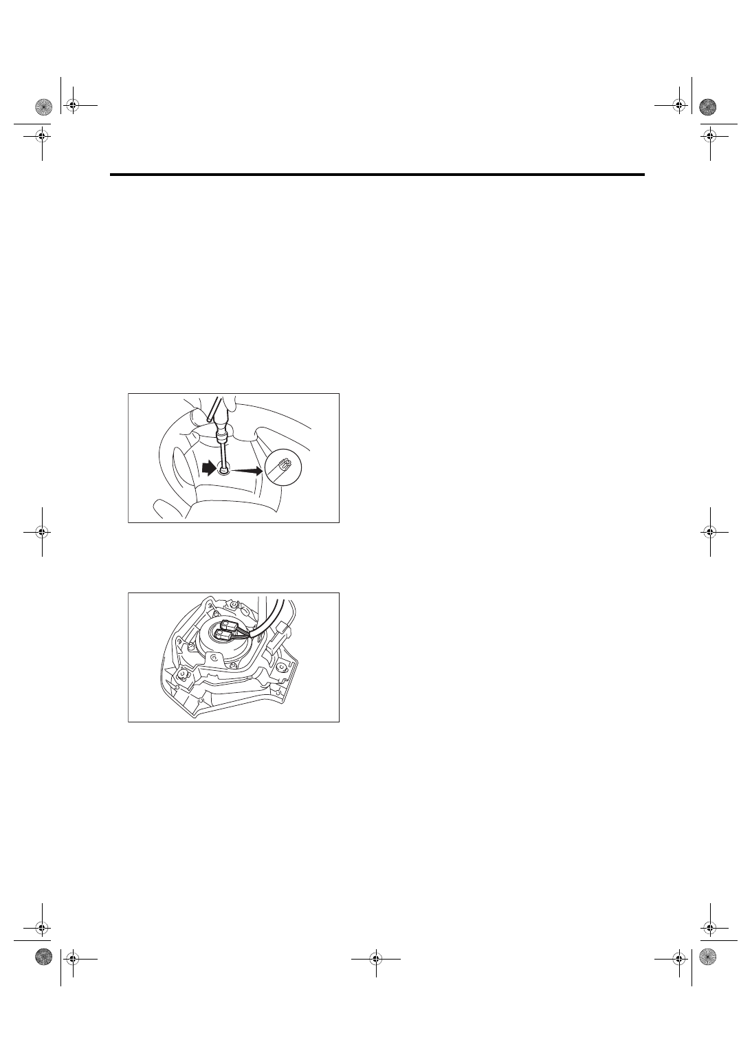
4) Using TORX
®
bit T30 (1), remove the two
TORX
®
bolts on the side of the steering wheel.
5) Disconnect the horn harness.
6) Disconnect the airbag connector on the back of
airbag module, and then remove the airbag mod-
ule. <Ref. to AB-8, PROCEDURE, Airbag Connec-
7) For handling of the removed airbag module, re-
fer to “CAUTION”. <Ref. to AB-5, CAUTION, Gen-
B: INSTALLATION
CAUTION:
• Refer to “CAUTION” of “General Description”
before handling the airbag module. <Ref. to AB-
5, CAUTION, General Description.>
• Do not allow harness and connectors to in-
terfere or get tangled up with other parts.
Install each part in the reverse order of removal.
Tightening torque:
10 N·m (1.02 kgf-m, 7.4 ft-lb)
C: INSPECTION
CAUTION:
• Refer to “CAUTION” of “General Description”
before handling the airbag module. <Ref. to AB-
5, CAUTION, General Description.>
• Do not allow harness and connectors to in-
terfere or get tangled up with other parts.
Check for the following, and replace the damaged
parts with new parts. <Ref. to AB-12, DRIVER’S
AIRBAG MODULE, INSPECTION, Inspection Lo-
• Airbag module
• Harness
• Connector
• Mounting bracket
CC-00018
(1)
AB-00622