Subaru Impreza 3 / Impreza WRX / Impreza WRX STI. Manual - part 581


  Index      Subaru     Subaru Impreza 3 / Impreza WRX / Impreza WRX STI - service repair manual 2008-2014 year


Search            


Content   ..  579  580  581  582   ..


Subaru Impreza 3 / Impreza WRX / Impreza WRX STI. Manual - part 581


PS-45

Oil Pump

POWER ASSISTED SYSTEM (POWER STEERING)

7. Oil Pump

A: REMOVAL

1) Disconnect the ground cable from battery.

2) Remove the V-belts (front side belt).

• Except for STI model: <Ref. to ME(w/o STI)-38,

REMOVAL, V-belt.>

• STI model: <Ref. to ME(STI)-40, REMOVAL, V-

belt.>

3) Disconnect  the  connector  from  power  steering

pump switch.

4) Disconnect the pressure hose and suction hose

from the oil pump.
CAUTION:

• Do not allow fluid to come into contact with

the pulley belt.

• To prevent foreign matter from entering the

hose and pipe, cover the open ends with clean

cloth.

5) Remove the installation bolt of the power steer-

ing pump bracket.

6) Place the oil pump bracket in a vise, and remove

the two bolts from the front side of the oil pump.
CAUTION:

When securing the oil pump bracket in a vice,

hold the oil pump bracket with the least possi-

ble force between two pieces of wood.

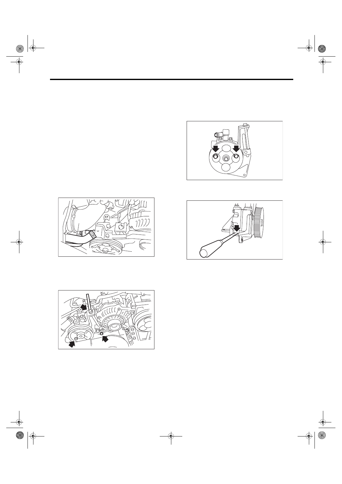
7) Remove the bolt from the rear side of oil pump.

8) Disassemble the oil pump and bracket by insert-

ing a flat tip screwdriver as shown in the figure.

(1) Suction hose
(2) Pressure hose

PS-00459

(2)

(1)

PS-00188

PS-00128

PS-00129

PS-46

Oil Pump

POWER ASSISTED SYSTEM (POWER STEERING)

B: INSTALLATION

1) Install the oil pump to bracket.

2) Tighten the bolts which hold the oil pump to the

bracket.
Tightening torque:

16 N·m (1.6 kgf-m, 11.8 ft-lb)

Tightening torque:

48 N·m (4.9 kgf-m, 35.4 ft-lb)

3) Attach the installation bolts of the power steering

pump bracket.
Tightening torque:

Refer to “COMPONENT” of “General Descrip-

tion”. <Ref. to PS-7, OIL PUMP, COMPO-

NENT, General Description.>

4) Connect the pressure hose and suction hose.
CAUTION:

Be careful when installing; If the hose is twisted

it may come into contact with other parts.
Tightening torque:

Eye bolt

40 N·m (4.1 kgf-m, 29.5 ft-lb)

5) Connect the power steering pump switch to the

connector.

6) After installing the oil pump, fill the oil pump with

fluid while rotating the pulley by hand and bleed the

air from the oil pump.
CAUTION:

Always fill the oil pump with the fluid to prevent

abnormal noise and seizure of the oil pump.

7) Install the V-belts (front side belt).

• Except for STI model: <Ref. to ME(w/o STI)-38,

INSTALLATION, V-belt.>

• STI  model:  <Ref.  to  ME(STI)-40,  INSTALLA-

TION, V-belt.>

8) Connect the battery ground terminal.

9) Fill with the specified power steering fluid. <Ref.

to PS-51, Power Steering Fluid.>
CAUTION:

Never start the engine before filling with fluid;

otherwise the vane pump may become seized.

PS-00128

PS-00137

PS-00188

(1) Suction hose
(2) Pressure hose

PS-00459

(2)

(1)

PS-47

Oil Pump

POWER ASSISTED SYSTEM (POWER STEERING)

C: INSPECTION

1. BASIC INSPECTION

Perform the following inspection procedures and replace faulty parts.

2. SERVICE LIMIT

Make a measurements as follows. If it exceeds the service limit, replace with a new part.
CAUTION:

• When securing the oil pump in a vice, hold the oil pump with the least possible force between two

pieces of wood.

• Do not set the outside of flow control valve or pulley on a vise; otherwise outside or pulley might

be deformed. Select properly sized wood pieces.

1) Play of the pulley shaft
Condition:

P: When applying a force of 9.8 N (1.0 kgf, 2.2 lbf)

Service limit:

Play in the radial direction (Direction    )

0.2 mm (0.008 in) or less

Axial play (Direction    )

0.9 mm (0.035 in) or less

No.

Parts

Inspection

Corrective action

1

Oil pump (exterior)

(1) Crack, damage or oil leakage

Replace the oil pump with a new part.

(2) Play of pulley shaft

Measure the radial play and axial play.
If any of these exceeds the service limit, replace the 
oil pump with a new part.

2

Pulley

(1) Damage

Replace the oil pump with a new part.

(2) Bend

Measure the V groove deflection.
If it exceeds the service limit, replace the oil pump 
with a new part.

3

Oil pump (interior)

(1) Faulty or seized of vane pump

Check the rotating resistance of pulley.
If it exceeds the service limit, replace the oil pump 
with a new part.

(2) Bend in the shaft or damage to 
bearing

If the a string is wrapped on the pulley and rotated, 
and the oil pump emits a noise that is markedly differ-
ent in tone and loudness from a sound of a new oil 
pump, replace the oil pump with a new part.

4

O-ring

Cracking or deterioration

Replace with a new part.

5

Bracket

Cracks

Replace with a new part.

(1) Dial gauge

P

(1)

PS-00145

(1) Dial gauge

P

(1)

PS-00146

PS-48

Oil Pump

POWER ASSISTED SYSTEM (POWER STEERING)

2) Deflection of the pulley groove
Service limit:

1.0 mm (0.039 in) or less

NOTE:

Read the value on one surface of V groove, set the

dial gauge on the other surface, and read the value

of the dial gauge.

3) Rotating resistance of pulley
Service limit:

Maximum load: 9.22 N (0.94 kgf, 2.07 lbf) or 

less

NOTE:

• A rather higher value may be indicated when pul-

ley starts turning.

• Measure the load during rotation to make a judg-

ment.

3. HYDRAULIC PRESSURE

NOTE:

• To  measure  hydraulic  pressure  correctly,  be

sure  to  complete  all  the  items  in  “INSPECTION”,

prior to performing the measurement. <Ref. to PS-

52, INSPECTION, General Diagnostic Table.>

• Do not leave the valve of pressure gauge closed

or hold the steering wheel at lock for 5 seconds or

more in any case, this can damage the oil pump.

• Before attaching a pressure gauge, place cloth

at locations where fluid is expected to spill. Wipe off

any spilt fluid completely after the measurement.

1) Regular pressure measurement

(1) Connect the ST1, ST2 and ST3.

ST1 925711000

PRESSURE GAUGE

ST2 34099AC020 ADAPTER HOSE B

ST3 34099AC010 ADAPTER HOSE A

(2) Remove the air intake duct.

• Except for STI model: <Ref. to IN(w/o STI)-

10, REMOVAL, Air Intake Duct.>

• STI model: <Ref. to IN(STI)-10, REMOVAL,

Air Intake Duct.>

(3) Disconnect  the  pressure  hose  from  the

pump.

(4) Using  the  gasket  (Part  No.  34621AC021)

and bolt (Part No. 34620AC010), install the ST2

to pump instead of pressure hose.

(5) Attach the ST3 to the end of pressure hose

which is removed from pump.

(6) Replenish  power  steering  fluid  up  to  the

specified level.

(7) Open the valve, and start the engine.

(1) Dial gauge

(1) Spring scale

PS-00147

PS-00148

(1) Suction hose
(2) Pressure hose

PS-00459

(2)

(1)


Content   ..  579  580  581  582   ..