Subaru Impreza 3 / Impreza WRX / Impreza WRX STI. Manual - part 579
PS-37
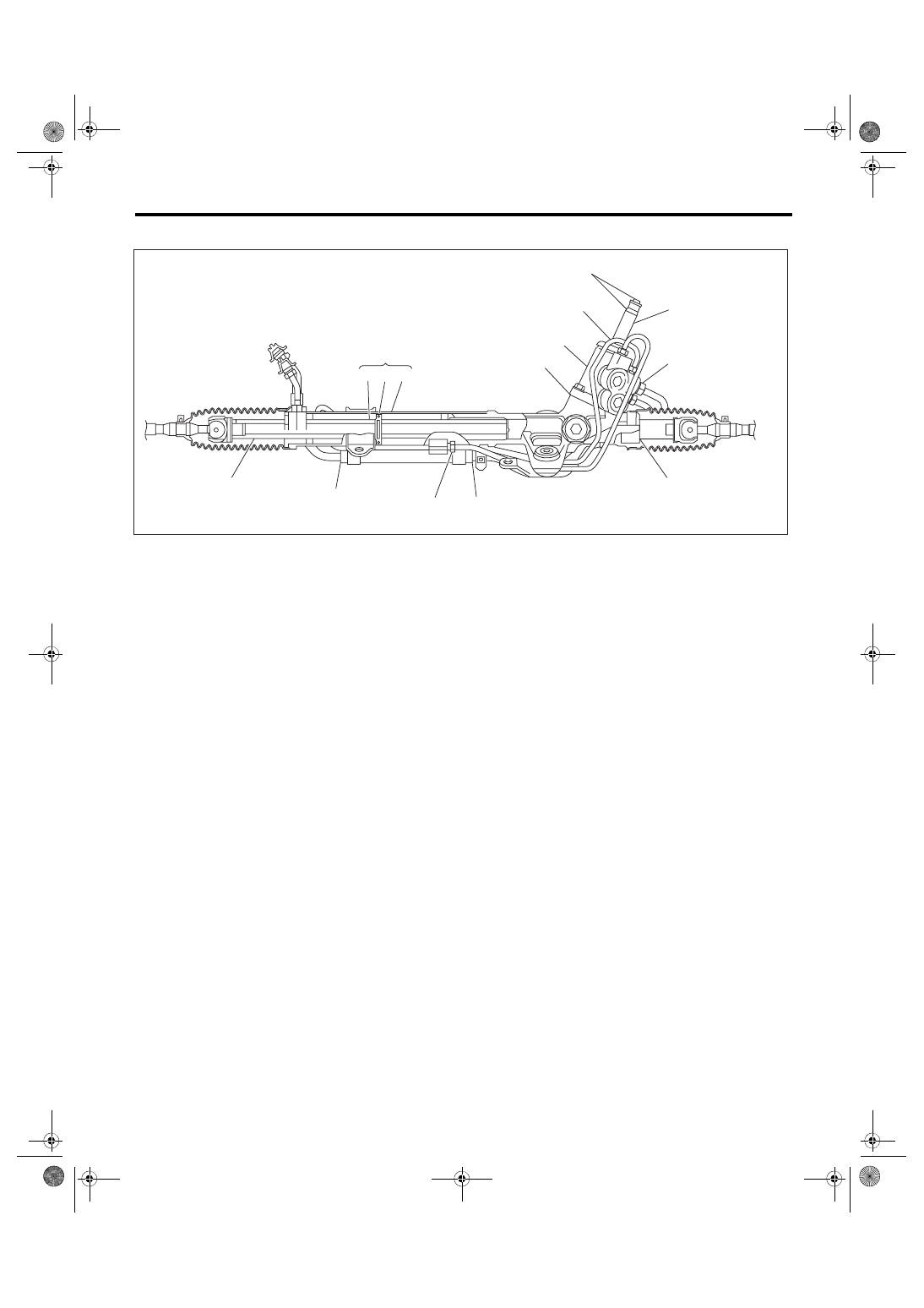
Steering Gearbox
POWER ASSISTED SYSTEM (POWER STEERING)
6. FLUID LEAKAGE
1) Lift up the vehicle.
2) If a fluid leak is found, clean the fluid completely
from the suspect area, and turn the steering wheel
30 to 40 times to the left and right from lock to lock,
with the engine running, and check again for leaks
immediately, and also after a few hours have
passed.
3) Cause and solution for oil leakage from “a”
The oil seal is damaged. Replace the valve assem-
bly or valve housing side oil seal assembly with a
new part.
4) Cause and solution for oil leakage from “b”
The torsion bar O-ring is damaged. Replace the
valve assembly with a new part.
5) Cause and solution for oil leakage from “c”
The oil seal is damaged. Replace the valve assem-
bly or pinion side oil seal with a new part.
6) Cause and solution for oil leakage from “d”
The pipe is damaged. Replace the faulty pipe or O-
ring.
7) Cause and solution for oil leakage from “g”
The hose is damaged. Replace the hose with a
new part.
8) If leak is other than a, b, c, d or g, or if oil is leak-
ing from gearbox, move the right and left boots to-
ward tie-rod end side, respectively, with the
gearbox mounted to the vehicle, and remove fluid
from surrounding portions. Then, turn the steering
wheel from lock to lock about 30 to 40 times with
the engine running, then re-inspect the leaking
area immediately after and several hours after this
operation.
(1) Leakage from “e”
The cylinder seal is damaged. Replace the oil
seal.
(2) Leakage from “f”
There are two possible causes. Perform the fol-
lowing step first. Remove the pipe assembly B
from the valve housing, and close the circuit us-
ing ST.
ST 926420000
PLUG
Turn the steering wheel from lock to lock ap-
prox. 30 to 40 times with the engine running,
then inspect the leaked portion immediately af-
ter and several hours after this operation.
• If leakage from “f” is noted again:
The oil seal of pinion and valve assembly is dam-
aged. Replace the pinion & valve assembly with a
new part. Or, replace the oil seal.
• If oil stops leaking from “f”:
The oil seal of rack housing is damaged. Replace
the oil seal and back-up ring.
(1)
Power cylinder
(3)
Rack piston
(5)
Input shaft
(2)
Cylinder
(4)
Rack axle
(6)
Valve housing
PS-00622
(4) (3) (2)
(5)
(6)
c
d
a
b
(1)
f
g
g
d
e