Subaru Impreza 3 / Impreza WRX / Impreza WRX STI. Manual - part 577


  Index      Subaru     Subaru Impreza 3 / Impreza WRX / Impreza WRX STI - service repair manual 2008-2014 year


Search            


Content   ..  575  576  577  578   ..


Subaru Impreza 3 / Impreza WRX / Impreza WRX STI. Manual - part 577


PS-29

Steering Gearbox

POWER ASSISTED SYSTEM (POWER STEERING)

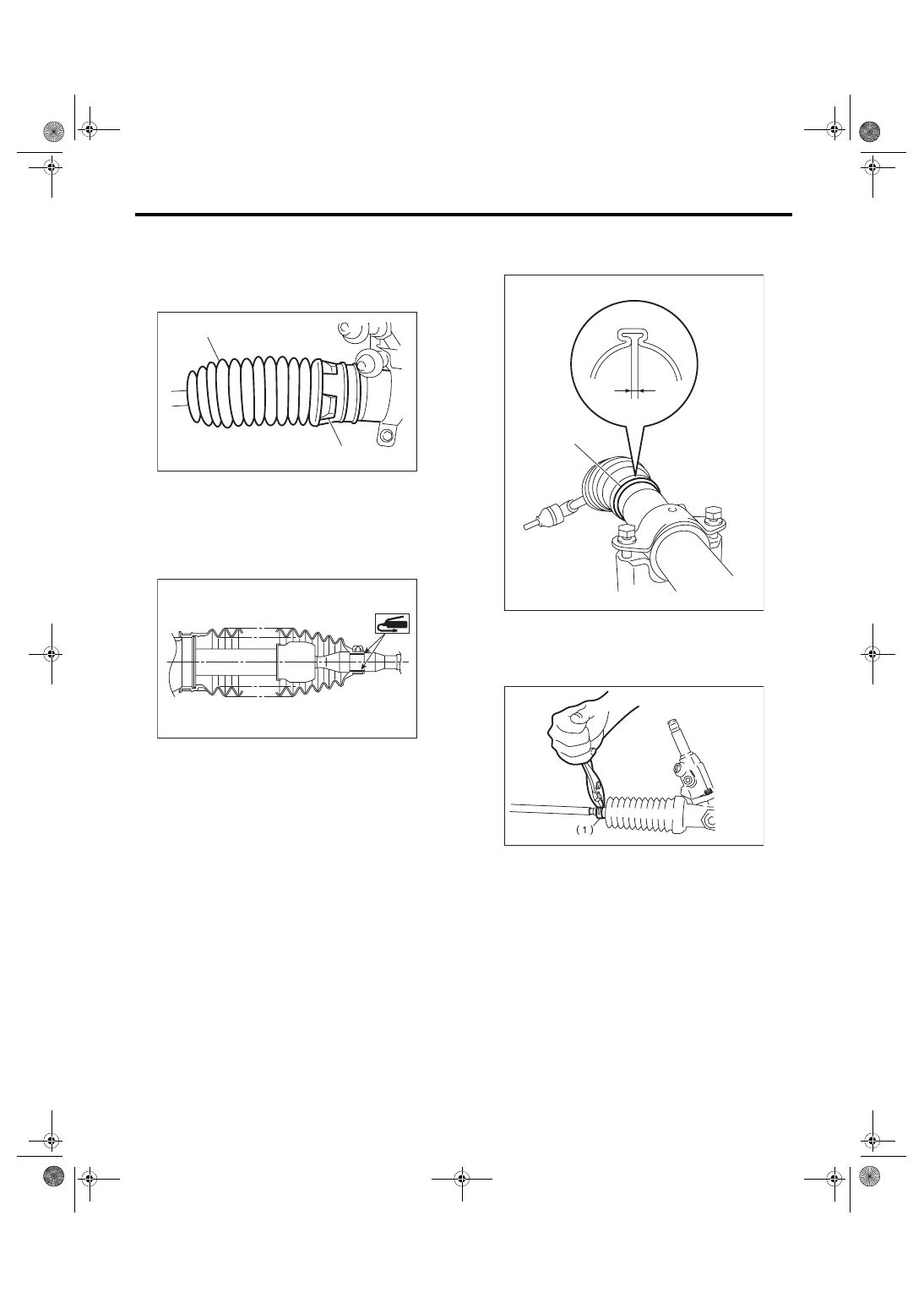
35) Apply  a  coat  of  grease  to  the  tie-rod  groove,

and then install the boot to the housing.
CAUTION:

Right side boot has groove for identification, be

sure to install the right and left of boot.

NOTE:

Make sure that the boot is installed without unusual

inflation or deflation.

36) Install a new boot band. Using band clamp pli-

ers, crimp it so that the clearance of crimping por-

tion becomes 2 mm (0.079 in) or less.

37) Fix the boot end with small clip.

38) After  installing,  check  that  the  boot  end  is  in-

stalled to the groove of the tie-rod.

(1) Right side boot
(2) Groove for identification

PS-00524

(2)

(1)

PS-00194

(A) Boot band
(B) 2 mm (0.079 in) or less

(1) Clip

PS-00499

(A)

(B)

PS-00053

PS-30

Steering Gearbox

POWER ASSISTED SYSTEM (POWER STEERING)

39) If the tie-rod end has been removed, screw in

lock nut and tie-rod end to the screwed portion of

tie-rod, and tighten the lock nut temporarily in a po-

sition as shown in the figure.
Installed tie-rod length L:

28 mm (1.1 in)

40) Inspect the gearbox as follows:

“A” Holding the tie-rod end, repeat lock to lock sev-

eral times as quickly as possible.

“B” Holding the tie-rod end, turn it slowly at a radius

several times as large as possible.

Finally, make sure that the boot is installed in the

specified position without inflating.

41) Remove the gearbox from ST.

ST1 926200000

STAND

ST2 34199AG000 BOSS D

42) Install the four pipes on gearbox.

(1) Connect the pipes A and B to the four pipe

joints of gearbox.

Tightening torque:

Cylinder side: 27 N·m (2.8 kgf-m, 19.9 ft-lb)

Gear housing side: 17 N·m (1.7 kgf-m, 12.5 ft-lb)

(2) Connect the feed pipe and return pipe to the

gearbox.

Tightening torque:

Feed pipe: 37 N·m (3.8 kgf-m, 27.3 ft-lb)

Return pipe: 29 N·m (3.0 kgf-m, 21.4 ft-lb)

2. CONTROL VALVE ASSEMBLY

Specified steering grease:

VALIANT GREASE M2

1) Clean all parts and tools before reassembling.

2) Apply a coat of specified power steering fluid to

the inner wall of valve housing.

3) Apply grease to the oil seal.

4) Verify the direction of oil seal.

L

PS-00097

B

A

PS-00098

(1) Feed pipe
(2) Return pipe

(1) Apply fluid.

PS-00525

(1)

(2)

PS-00169

(1)

PS-31

Steering Gearbox

POWER ASSISTED SYSTEM (POWER STEERING)

5) Using the ST and a press, install the oil seal and

the bushing in valve housing.

ST 34199AG090 INSTALLER & REMOVER

6) Apply vinyl tape to the groove of pinion.

7) Install  the  wave  washer  and  oil  seal  to  pinion,

and then remove the vinyl tape.

8) Attach the ST to pinion, and install the seal ring

and O-ring.

ST 34199AG020 GUIDE

9) Remove the ST GUIDE, and form the seal ring

properly using ST FORMER.

ST 34199AG070 FORMER

10) Put vinyl tape around pinion shaft spline to pro-

tect oil seal from damage.

11) Install the valve to pinion, and install the snap

ring.

12) Attach  the  pinion  &  valve  assembly  into  the

valve housing.

(1) Bushing
(2) Oil seal

(1) Oil seal
(2) Vinyl tape
(3) Wave washer

(1) Seal ring and O-ring

PS-00856

(2)

(1)

ST

PS-00528

(1)

(2)

(3)

PS-00529

(1)

ST

(1) Seal ring

(1) Snap ring
(2) Valve

(1) Valve housing
(2) Pinion & valve ASSY

PS-00530

ST

(1)

PS-00531

(2)

(1)

PS-00532

(1)

(2)

PS-32

Steering Gearbox

POWER ASSISTED SYSTEM (POWER STEERING)

13) Using a press, push the outer race of bearing

and press-fit the pinion & valve assembly into hous-

ing.

14) Apply  the  specified  grease  to  the  dust  cover

and fill it to the clearance between pinion shaft and

housing.

15) Install the dust cover on valve assembly.
CAUTION:

Be  sure  to  install  the  dust  cover  to  groove  of

shaft.

16) Apply the genuine grease to the edge and body

of pinion gear and bearing of valve assembly.

17) Apply grease to a new O-ring and attach it to

the valve assembly.

18) Insert the valve assembly into place while fac-

ing the rack teeth toward pinion.
CAUTION:

Check that the needle bearing is not damaged.

Replace with a new steering gearbox if damage

is found.

19) Tighten the bolts alternately to secure the valve

assembly.
CAUTION:

Be sure to alternately tighten the bolts.
Tightening torque:

20 N·m (2.0 kgf-m, 14.8 ft-lb)

20) Apply liquid gasket to 1/3 or more of entire pe-

rimeter of adjusting screw thread.
Liquid gasket:

THREE BOND 1102 or THREE BOND 1215

(1) Pinion & valve ASSY
(2) Bearing
(3) Housing

(1) Dust cover
(2) Groove

PS-00533

(1)

(2)

(3)

PS-01675

(1)

(2)

PS-01674

(1) O-ring

PS-01676

(1)

PS-00143


Content   ..  575  576  577  578   ..