Subaru Impreza 3 / Impreza WRX / Impreza WRX STI. Manual - part 582
 

  Index      Subaru     Subaru Impreza 3 / Impreza WRX / Impreza WRX STI - service repair manual 2008-2014 year


Search            


Content   ..  580  581  582  583   ..


Subaru Impreza 3 / Impreza WRX / Impreza WRX STI. Manual - part 582


PS-49

Oil Pump

POWER ASSISTED SYSTEM (POWER STEERING)

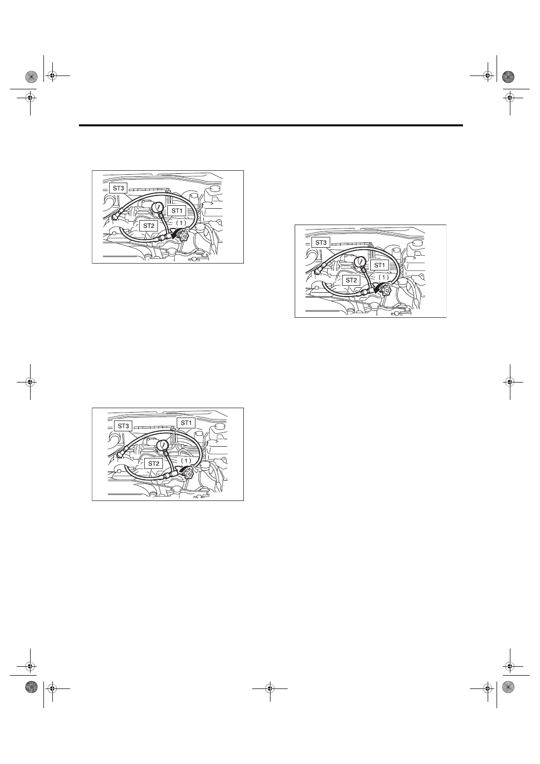
(8) Measure the regular pressure.

ST1 925711000

PRESSURE GAUGE

ST2 34099AC020 ADAPTER HOSE B

ST3 34099AC010 ADAPTER HOSE A

Service limit:

981 kPa (10 kgf/cm

2

, 142 psi) or less

(9) If it is not within the specification, replace the

faulty part for the following problems. (Pipe or

hose clogged, leaks from fluid line, and mixture

of foreign matter in fluid line)

2) Measure the relief pressure.

(1) Using the ST, measure the relief pressure.

(2) Close the valve.

(3) Measure the relief pressure.

ST1 925711000

PRESSURE GAUGE

ST2 34099AC020 ADAPTER HOSE B

ST3 34099AC010 ADAPTER HOSE A

Service limit:

STI model

8,300 — 9,000 kPa (85 — 92 kgf/cm

2

, 1,203 

— 1,305 psi)

Except for STI model

8,100 — 8,800 kPa (83 — 90 kgf/cm

2

, 1,174 

— 1,276 psi)

(4) If the torque is not within specified range, re-

place the oil pump.

3) Measure the working pressure.

(1) Using  the  ST,  measure  the  working  pres-

sure.

(2) Open the valve.

(3) Measure  the  working  pressure  of  control

valve  by  turning  steering  wheel  from  stop  to

stop.

ST1 925711000

PRESSURE GAUGE

ST2 34099AC020 ADAPTER HOSE B

ST3 34099AC010 ADAPTER HOSE A

Service limit:

STI model

8,300 — 9,000 kPa (85 — 92 kgf/cm

2

, 1,203 

— 1,305 psi)

Except for STI model

8,100 — 8,800 kPa (83 — 90 kgf/cm

2

, 1,174 

— 1,276 psi)

(4) If  it  is  out  of  specification,  measure  the

steering  effort.  <Ref.  to  PS-55,  MEASURE-

MENT  OF  STEERING  EFFORT,  INSPEC-

TION, General Diagnostic Table.>

If it is not within specification, replace the con-

trol valve itself or control valve and pinion as a

single unit, using new parts.

(1) Valve

(1) Valve

PS-00152

PS-00153

(1) Valve

PS-00152

PS-50

Reservoir Tank

POWER ASSISTED SYSTEM (POWER STEERING)

8. Reservoir Tank

A: REMOVAL

1) Drain fluid from the reservoir tank.

2) Disconnect the hose from reservoir tank.
CAUTION:

To  prevent  foreign  matter  from  entering  the

hose  and  pipe,  cover  the  open  ends  of  them

with clean cloth.

3) Remove the reservoir tank from the body.

B: INSTALLATION

1) Install the reservoir tank to the body.
Tightening torque:

13 N·m (1.3 kgf-m, 9.6 ft-lb)

2) Connect the hose to the reservoir tank.

3) Replenish power steering fluid up to the speci-

fied  level.  <Ref.  to  PS-51,  INSPECTION,  Power

Steering Fluid.>

C: INSPECTION

Check  the  reservoir  tank  for  cracks,  breakage  or

damage. If a failure is found, replace the reservoir

tank.

(1) Reservoir tank
(2) Suction hose
(3) Return hose

(1) Reservoir tank
(2) Suction hose
(3) Return hose

PS-00799

(3)

(1)

(2)

PS-00799

(3)

(1)

(2)

PS-51

Power Steering Fluid

POWER ASSISTED SYSTEM (POWER STEERING)

9. Power Steering Fluid

A: SPECIFICATION

B: INSPECTION

1) Check the power steering fluid for deterioration

or contamination. If the fluid is highly deteriorated

or contaminated, drain it and refill with new fluid.

2) Check the joints and units for oil leakage. If any

oil leaks are found, repair or replace the applicable

part.

3) Inspect the fluid level of reservoir tank with vehi-

cle on level surface and engine stopped.

If the level is at “MIN.” point or below, add fluid to

keep the level in the specified range of the indica-

tor. If at “MAX”. point or above, drain fluid by using

a syringe or the like.

(1) Check  at  power  steering  fluid  temperature

20°C (68°F); read the fluid level on the “COLD”

side.

(2) Check  at  power  steering  fluid  temperature

80°C (176°F); read the fluid level on the “HOT”

side.

C: REPLACEMENT

1) Lift up the vehicle.

2) Remove  the  under  cover.  <Ref.  to  EI-28,  RE-

MOVAL, Front Under Cover.>

3) Remove the crossmember support.

4) Remove the pipe joint in the center of gearbox,

and  connect  the  vinyl  hose  to  the  pipe  and  joint.

Wipe fluid off while turning the steering wheel.

5) Add the specified fluid to reservoir tank at “MAX”

level.

6) Continue to turn the steering wheel slowly from

lock to lock until the bubbles stop appearing on oil

surface  while  keeping  the  fluid  at  the  level  in  the

step 4).

7) If the steering wheel is turned in a low fluid level

condition, air will be sucked into the pipe. If air has

entered, leave it for about half an hour and then re-

peat step 5) again.

8) Start the engine and let it idle.

9) Continue to turn the steering wheel slowly from

lock to lock again until the bubbles stop appearing

on oil surface, while keeping the fluid at the level in

step 4).

Normally bubbles will stop appearing after turning

the steering wheel from lock to lock three times.

10) In case bubbles do not stop appearing in the

tank, leave it for about half an hour and then repeat

from step 4) again.

11) Lower the vehicle, and then idle the engine.

12) Continue to turn the steering wheel from lock to

lock until the bubbles stop appearing and change of

the fluid level is within 3 mm (0.12 in).

13) In  case  the  following  happens,  leave  it  about

half an hour and then perform step 8) to 11) again.

(1) The fluid level changes by 3 mm (0.12 in) or

more.

(2) Bubbles remain on the upper surface of the

fluid.

(3) Grinding noise is generated from oil pump.

14) Check  the  fluid  leakage  after  turning  steering

wheel from lock to lock with engine running.

Recommended power steering fluid

SUBARU ATF or DEXRON III

PS-00463

HOT  MAX

COLD  MAX

HOT  MIN

COLD  MIN

PS-52

General Diagnostic Table

POWER ASSISTED SYSTEM (POWER STEERING)

10.General Diagnostic Table

A: INSPECTION

*

1 If the tires or wheels are wider than standard, the load to power steering system is increased. Accordingly, in a condition, for

example before fluid warms-up, relief valve may work before reaching maximum turning angle. In this case, steering effort may
be heavy. When the measured hydraulic pressure is normal, there is no abnormal thing.

*

2 In cold weather, steering effort may be heavy due to increased flow resistance of cold fluid. After warming-up engine, turn the

steering wheel from stop to stop several times to warm up fluid. If steering effort reduces normally, function is normal.

*

3 In cold weather or with insufficient warm up of the engine, steering effort may be heavy due to excessive drop of idling when

turning the steering wheel. In this case, start the vehicle with increasing engine speed than usual. If steering effort reduces nor-
mally, function is normal.

Trouble

Possible cause

Corrective action

• Steering effort is heavy in 
all ranges.
• Steering effort is heavy at 
stand still.
• Steering wheel vibrates 
when turning.

1. Pulley belt
• Unequal length of pulley belts
• Contact with oil or grease
• Looseness or damage of the pulley belt
• Poor uniformity of the pulley belt cross section
• Pulley belt touches to pulley bottom
• Poor revolution of pulleys (except oil pump pulley)
• Poor revolution of oil pump pulley

Adjust or replace the 
faulty parts.

2. Tire and wheel
• Improper tire out of specifications

*

1

• Improper wheel out of specifications

*

1

• Tires not properly inflated

Replace or reinflate the 
tire and wheel.
Instruct customers.

3. Fluid
• Low fluid level
• Air entry in fluid
• Dust entry in fluid
• Fluid deterioration
• Inadequate warm up of fluid

*

2

Refill the fluid, bleed air, 
replace or instruct cus-
tomer.

4. Idle speed
• Lower idle speed
• Excessive drop of idle speed at start or when turning the steering 
wheel

*

3

Adjust the idle speed or 
instruct customer.

5. Measure the hydraulic pressure. <Ref. to PS-47, INSPECTION, Oil 
Pump.>

Replace the faulty parts.

6. Measure the steering wheel effort. <Ref. to PS-55, MEASUREMENT 
OF STEERING EFFORT, INSPECTION, General Diagnostic Table.>

Adjust or replace the 
faulty parts.

7. Fluid line
• Folded hose
• Flattened pipe

Replace the faulty parts.

• Vehicle leads to one side 
or the other.
• Returning force of steering 
wheel to center is poor.
• Steering wheel vibrates 
when turning.

1. Tire and wheel
• Flat tire
• Mixed use of different tires
• Mixed use of different wheels
• Abnormal wear of tire
• Unequal tread remaining
• Unequal pressure of tire

Adjust, repair or replace 
the tire and wheel.

2. Front alignment
• Improper or unequal caster
• Improper or unequal toe-in
• Loose suspension connections

Adjust or retighten.

3. Others
• Damaged joint assembly
• Unbalance of ground clearance
• Unbalance of load

Replace or adjust the 
faulty parts, or instruct 
customer.

4. Measure the steering wheel effort. <Ref. to PS-55, MEASUREMENT 
OF STEERING EFFORT, INSPECTION, General Diagnostic Table.>

Adjust or replace the 
faulty parts.


Content   ..  580  581  582  583   ..