Subaru Impreza 3 / Impreza WRX / Impreza WRX STI. Manual - part 514


  Index      Subaru     Subaru Impreza 3 / Impreza WRX / Impreza WRX STI - service repair manual 2008-2014 year


Search            


Content   ..  512  513  514  515   ..


Subaru Impreza 3 / Impreza WRX / Impreza WRX STI. Manual - part 514


DS-29

Front Drive Shaft

DRIVE SHAFT SYSTEM

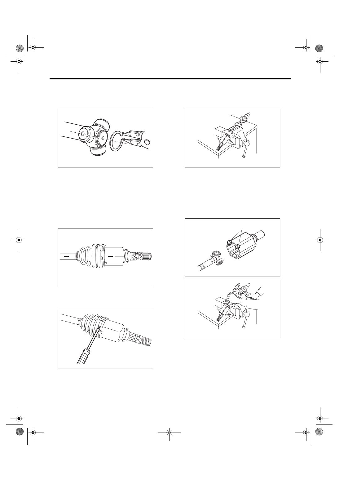
9) Remove the snap ring and trunnion.
CAUTION:

Be sure to wrap shaft splines with vinyl tape to

protect the boot from scratches.

10) Remove the PTJ boot.

11) Remove  the  O-ring  from  the  groove  of  the

shaft.
NOTE:

The EBJ is a non-disassembly part, so the axle dis-

assembly stops here.

2. STI MODEL

1) Place  alignment  marks  on  the  shaft  and  outer

race.

2) Remove the AAR boot band and boot.
CAUTION:

Be careful not to damage the boot.

3) Place  the  drive  shaft  between  wooden  blocks

and fix it on a vise.
CAUTION:

Do not set the only drive shaft on a vise.

4) Tap the staking are of the outer race alternately

with a plastic or wooden bar, and remove one roller

at a time.
CAUTION:

• Tap the staking area (A) of the outer race.

• Do not use a metal bar as the outer race may

deform.

• Be careful not to damage the roller parts.

5) Remove the outer race from shaft assembly.
CAUTION:

Make sure to have your associate held the outer

race when removing the third roller to prevent

the outer race from falling.

6) Wipe off grease.
CAUTION:

The grease is a special type of grease. Do not

mix with other grease.

DS-00111

DS-00106

DS-00107

DS-00417

DS-00419

(A)

DS-00418

DS-30

Front Drive Shaft

DRIVE SHAFT SYSTEM

7) Place alignment marks on the roller kit and trun-

nion.

8) Remove the roller kit from trunnion.
CAUTION:

Be careful with the roller kit position.

9) Place  alignment  marks  on  the  trunnion  and

shaft.

10) Remove the snap ring and trunnion.
CAUTION:

Be sure to wrap shaft splines with vinyl tape to

protect the boot from scratches.

11) Remove the AAR boot.
NOTE:

The  AC  is  a  non-disassembly  part,  so  the  drive

shaft disassembly stops here.

D: ASSEMBLY

1. EXCEPT FOR STI MODEL

1) Roll up a thick piece of paper to a size where the

shaft can pass through, and affix with tape to form

a cylinder.

2) Attach a new O-ring on this cylinder.
CAUTION:

• Always use a new O-ring.

• Be careful that the O-ring does not become

scratched and that there are no foreign objects

attached to it.

• Make sure to install the O-ring so that it does

not twist as much as possible.

• Do not stretch the O-ring to 30 mm (1.18 in)

inner diameter or more.

3) Pass  the  cylinder  material  onto  the  shaft,  and

slide in the direction of the shaft axis.

4) Clean  the  shaft  boot  groove,  and  wipe  off  the

grease.

DS-00109

DS-00110

DS-00111

(1) O-ring
(2) Cylinder made with thick paper, etc.

(1) Cylinder material
(2) O-ring
(3) Shaft

DS-00451

(1)

(2)

DS-00452

(1)

(2)

(3)

DS-31

Front Drive Shaft

DRIVE SHAFT SYSTEM

5) Slide  the  cylinder  material  near  the  shaft  boot

groove, and move the O-ring from the cylinder ma-

terial onto the shaft boot groove.
CAUTION:

• Attach  the  O-ring  to  the  shaft  boot  groove

center.

• Be careful that the O-ring does not become

scratched and that there are no foreign objects

attached to it.

• Make sure to install the O-ring so that it does

not twist as much as possible.

• With  the  O-ring  attached,  do  not  wash  with

kerosene, gasoline, etc.

6) Pass the PTJ small diameter boot band through

the shaft.

7) Wrap vinyl tape around the splines of the shaft.
CAUTION:

To prevent damage to the boots, make sure to

always wrap with vinyl tape for protection.

8) Install a new PTJ boot.
CAUTION:

Make sure to fit securely on the boot groove of

the shaft.

9) Match the alignment marks, and attach the trun-

nion onto the shaft.

10) Attach the snap ring to the shaft.
CAUTION:

Confirm that the snap ring is completely fitted

in the shaft groove.

11) Fill 100 to 110 g (3.53 to 3.88 oz) of specified

grease into the interior of the PTJ outer race.
Grease:

NKG302

(1) Shaft
(2) Cylinder material
(3) O-ring
(4) Boot groove

(1)

(2)

(3)

(1)

(4)

DS-00453

(1) PTJ boot
(2) O-ring
(3) Boot groove

(1)

(3)

(2)

DS-00454

DS-00110

DS-32

Front Drive Shaft

DRIVE SHAFT SYSTEM

12) Apply a thin coat of specified grease to the roll-

er kit and trunnion.

13) Match the alignment marks of the roller kit and

trunnion, and attach the roller kit.
CAUTION:

Be careful with the roller kit position.

14) Match  the  alignment  marks  of  the  shaft  and

outer race, and attach the outer race.

15) Install the snap ring in the groove of the PTJ

outer race.
CAUTION:

Pull  the  shaft  lightly  and  make  sure  that  the

snap ring is completely fitted in the groove.

16) Apply an even coat of the specified grease 30

to 40 g (1.06 to 1.41 oz) to the entire inner surface

of boot.

17) Attach the PTJ boot taking care not to twist it.
CAUTION:

• Clean the large end of PTJ boot and the boot

groove well, and remove the grease and other

substances.

• When  installing  the  PTJ  boot,  position  the

outer race of the PTJ at center of the stroke.

18) Set the new boot band at the specified position.

19) Tighten  the  boot  bands  using  ST,  torque

wrench and socket flex handle.

ST 28099AC000 BOOT BAND PLIER
CAUTION:

The large boot band is to be tightened so that

the omega shaped part is at the position indi-

cated in the figure below.

Tightening torque:

Large boot band

178 N·m (18.2 kgf-m, 131.3 ft-lb)

Small boot band

145 N·m (14.8 kgf-m, 106.9 ft-lb)

20) Extend and retract the PTJ repeatedly so that

grease is spread evenly.

DS-00109

DS-00106

(1) Omega shaped part
(2) Boot band
(3) Outer race

(A) Large boot band
(B) Boot

(C) Torque wrench
(D) Socket flex handle

(E) Outer race

DS-00456

(1)

(2)

(3)

DS-00120

ST

(A)

(B)

(C)

(D)

(E)

ONL

Y


Content   ..  512  513  514  515   ..