Subaru Impreza 3 / Impreza WRX / Impreza WRX STI. Manual - part 515
 

  Index      Subaru     Subaru Impreza 3 / Impreza WRX / Impreza WRX STI - service repair manual 2008-2014 year


Search            


Content   ..  513  514  515  516   ..


Subaru Impreza 3 / Impreza WRX / Impreza WRX STI. Manual - part 515


DS-33

Front Drive Shaft

DRIVE SHAFT SYSTEM

2. STI MODEL

NOTE:

Use specified grease.
AAR side:

ONE LUBER C

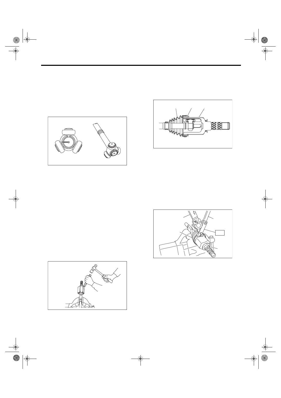
1) Pass the AAR boot through the shaft.

2) Align alignment marks and install the trunnion on

the shaft. Install the snap ring into the shaft groove

securely.

3) Fill  50  to  60  g  (1.76  to  2.12  oz)  of  specified

grease into the interior of AAR outer race.

4) Apply a thin coat of specified grease to the roller

and trunnion.

5) Place  the  drive  shaft  between  wooden  blocks

and fix it on a vise.
CAUTION:

Do not set the only drive shaft on a vise.

6) Align the alignment marks on the shaft and outer

race.

7) Tap the insertion upper part of the outer race al-

ternately using a plastic or wood bar shown in the

figure, and then insert the roller one by one.
CAUTION:

• Do not use a metal bar as the outer race may

deform.

• Do  not  tap  on  the  end  of  outer  race  (shaft

part).

• Be careful not to deform the baffle plate.

8) Apply an even coat of the specified grease 30 to

40 g (1.06 to 1.41 oz) to the entire inner surface of

boot.

9) Install  the  AAR  boot  and  grommet  taking  care

not to twist it.
CAUTION:

• Replace the boot and grommet as a set.

• Do not let grease get on groove of the outer

race side.

10) Insert a flat tip screwdriver, etc. between outer

race and grommet to make pressure inside of boot

as high as barometric pressure.

11) Install the new large boot band and small boot

band at the required positions.

12) Tighten  the  boot  bands  using  ST,  torque

wrench and socket flex handle.

ST 28099AC000 BOOT BAND PLIER

Clearance at the crimped section of the boot 

band:

Large boot band

1 mm (0.04 in) or less

Small boot band

1 mm (0.04 in) or less

13) Extend and retract the AAR repeatedly to pro-

vide an equal coating of grease.

DS-00110

DS-00420

(1) Outer race
(2) Grommet
(3) Boot

(A) Large boot band
(B) Boot

(C) Torque wrench
(D) Socket flex handle

(E) AAR

(3)

(2)

(1)

DS-00444

DS-00120

ST

(A)

(B)

(C)

(D)

(E)

ONL

Y

DS-34

Front Drive Shaft

DRIVE SHAFT SYSTEM

E: INSPECTION

Check the removed parts for damage, wear, corro-

sion etc. If faulty, repair or replace.

• PTJ (pillow tripod joint)

Check  for  seizure,  corrosion,  damage,  wear  and

excessive play.

• EBJ (high-efficiency compact ball fixed joint)

Check for seizure, corrosion, damage and exces-

sive play.

• AAR and AC

Check  for  seizure,  corrosion,  damage,  wear  and

excessive play.

• Shaft

Check  for  excessive  bending,  twisting,  damage

and wear.

• Boot

Check for wear, warping, breakage and scratches.

• Grease

Check for discoloration and fluidity.

DS-35

Rear Drive Shaft

DRIVE SHAFT SYSTEM

8. Rear Drive Shaft

A: REMOVAL

1) Disconnect the ground cable from battery.

2) Lift  up  the  vehicle,  and  then  remove  the  rear

wheels.

3) Lift the crimped section of axle nut.

4) Remove  the  axle  nut  using  a  socket  wrench

while depressing the brake pedal.
CAUTION:

Do not loosen the axle nut while the rear axle is

loaded. Doing so may damage the hub bearing.

5) Drain differential gear oil.

6) Remove  the  rear  trailing  link.  <Ref.  to  RS-10,

REMOVAL, Rear Trailing Link.>

7) Remove the rear lateral link. <Ref. to RS-16, RE-

MOVAL, Rear Lateral Link.>

8) Remove the rear drive shaft from the rear differ-

ential by using the ST.

ST 28099PA100 DRIVE SHAFT REMOVER
NOTE:

Fit the ST to the bolts as shown in the figure to pre-

vent damage of the side bearing retainer.

9) Remove the rear drive shaft from the rear axle. If

it is hard to remove, use ST1 and ST2.

ST1 926470000

AXLE SHAFT PULLER

ST2 28099PA110

AXLE SHAFT PULLER 

PLATE

DS-00038

(A) Bolt

DI-00491

(A)

ST

DS-00122

ST2

ST1

DS-36

Rear Drive Shaft

DRIVE SHAFT SYSTEM

B: INSTALLATION

1) Replace the rear differential side oil seal. <Ref.

to  DI-56,  REPLACEMENT,  Rear  Differential  Side

Oil Seal.>
NOTE:

After pulling out the drive shaft, be sure to replace

with a new oil seal.

2) Insert the EBJ into rear hub splines.
CAUTION:

• Be  careful  not  to  damage  the  magnetic  en-

coder.

• Do  not  get  closer  the  tool  which  charged

magnetism to magnetic encoder.

3) Draw the rear drive shaft into specified position.
CAUTION:

Do not hammer drive shaft when installing it.

4) Tighten the axle nut temporarily.

5) Using the ST, install the rear drive shaft to the

rear differential.

ST 28099PA090 OIL SEAL PROTECTOR

6) Attach the links to the rear housing and tighten

them to the specified torque.
CAUTION:

For parts which are not reusable, refer to COM-

PONENT. <Ref. to RS-3, COMPONENT, General

Description.>
Tightening torque:

Stabilizer link

38 N·m (3.87 kgf-m, 28 ft-lb)

Shock absorber

80 N·m (8.16 kgf-m, 59 ft-lb)

Rear lateral link

80 N·m (8.16 kgf-m, 59 ft-lb)

Trailing link

90 N·m (9.18 kgf-m, 66.4 ft-lb)

7) While pressing the brake pedal, tighten the new

axle nuts to the specified torque.
CAUTION:

Do  not  apply  weight  to  the  rear  axle  before

tightening the axle nut. Doing so may damage

the hub bearing.
Tightening torque:

190 N·m (19.37 kgf-m, 140.1 ft-lb)

8) Lock the axle nut securely.

9) Fill differential gear oil.

10) Install the rear wheels.
Tightening torque:

100 N·m (10.20 kgf-m, 73.8 ft-lb)

11) Connect the battery ground terminal.

12) Inspect the wheel alignment and adjust if nec-

essary.

(1) Magnetic encoder
(2) Rear hub unit bearing

DS-00251

(2)

(1)

ST

DI-00223

DS-00048


Content   ..  513  514  515  516   ..