Subaru Impreza 3 / Impreza WRX / Impreza WRX STI. Manual - part 513
DS-25
Rear Hub Unit Bearing
DRIVE SHAFT SYSTEM
B: INSTALLATION
1) Aligning with the mounting hole of the rear brake
back plate, temporarily tighten the rear hub unit
bearing to the rear housing.
CAUTION:
• Be careful not to damage the magnetic en-
coder.
• Do not get closer the tool which charged
magnetism to magnetic encoder.
2) Tighten the four bolts of the rear housing.
Tightening torque:
65 N·m (6.63 kgf-m, 47.9 ft-lb)
3) Tighten the new axle nut temporarily.
4) Install the rear disc rotor.
5) Install the disc brake caliper on the rear housing.
Tightening torque:
17-inch type
65 N·m (6.63 kgf-m, 47.9 ft-lb)
15-inch type
66 N·m (6.73 kgf-m, 48.7 ft-lb)
6) While pressing the brake pedal, tighten the new
axle nuts to the specified torque.
Tightening torque:
190 N·m (19.4 kgf-m, 140.1 ft-lb)
CAUTION:
Do not apply weight to the rear axle before
tightening the axle nut. Doing so may damage
the hub bearing.
7) After tightening the axle nut, lock it securely.
8) Install the rear wheels.
Tightening torque:
100 N·m (10.20 kgf-m, 73.8 ft-lb)
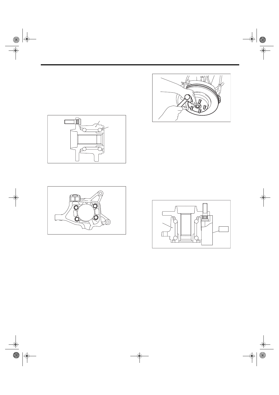
C: DISASSEMBLY
Using the ST and a hydraulic press, push out the
hub bolts.
CAUTION:
• Be careful not to hammer the hub bolts. This
may deform the hub.
• Do not reuse the hub bolt.
ST 28399AG000 HUB STAND
NOTE:
Since the hub unit bearing can not be disassem-
bled, only hub bolts can be removed.
(1) Magnetic encoder
(2) Rear hub unit bearing
DS-00251
(2)
(1)
DS-00414
(1) Rear hub unit bearing
DS-00048
DS-00254
ST
(1)