Subaru Impreza 3 / Impreza WRX / Impreza WRX STI. Manual - part 512
 

  Index      Subaru     Subaru Impreza 3 / Impreza WRX / Impreza WRX STI - service repair manual 2008-2014 year


Search            


Content   ..  510  511  512  513   ..


Subaru Impreza 3 / Impreza WRX / Impreza WRX STI. Manual - part 512


DS-21

Rear Axle

DRIVE SHAFT SYSTEM

NOTE:

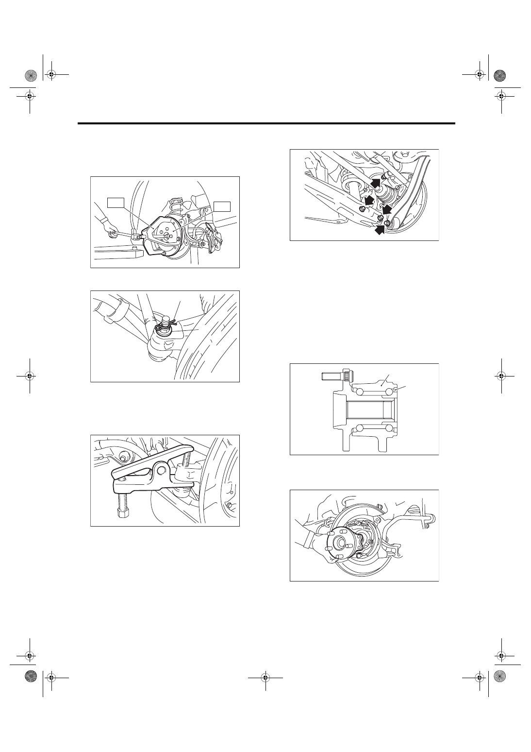
If it is hard to remove, use the ST.

ST1 926470000

AXLE SHAFT PULLER

ST2 28099PA110

AXLE SHAFT PULLER 

PLATE

10) Remove the snap pin and nut from the front lat-

eral link.

11) Separate the rear housing and the ball joint us-

ing the puller.

12) Separate the upper arm, trailing link and rear

lateral link from the rear housing.

13) Remove the rear axle.

B: INSTALLATION

1) Temporarily tighten the rear housing to the up-

per arm.

2) Aligning with the mounting hole of the rear brake

back  plate,  temporarily  tighten  the  rear  hub  unit

bearing to the rear housing.
CAUTION:

• Be  careful  not  to  damage  the  magnetic  en-

coder.

• Do  not  get  closer  the  tool  which  charged

magnetism to magnetic encoder.

3) Attach the rear drive shaft to the rear hub unit

bearing.

4) Tighten the new axle nut temporarily.
CAUTION:

Use new axle nuts.

(1) Snap pin
(2) Nut

DS-00122

ST2

ST1

(2)

(1)

RS-00189

RS-00190

(1) Magnetic encoder
(2) Rear hub unit bearing

DS-00415

DS-00251

(2)

(1)

DS-00360

DS-22

Rear Axle

DRIVE SHAFT SYSTEM

5) Attach the links to the rear housing and tighten

them to the specified torque.
CAUTION:

For parts which are not reusable, refer to COM-

PONENT. <Ref. to RS-3, COMPONENT, General

Description.>
Tightening torque:

Upper arm

80 N·m (8.16 kgf-m, 59 ft-lb)

Front lateral link

60 N·m (6.12 kgf-m, 44.3 ft-lb)

Rear lateral link

80 N·m (8.16 kgf-m, 59 ft-lb)

Trailing link

90 N·m (9.18 kgf-m, 66.4 ft-lb)

6) Tighten the four bolts of the rear housing.
Tightening torque:

65 N·m (6.63 kgf-m, 47.9 ft-lb)

7) Install the rear disc rotor.

8) Install  the  rear  disc  brake  caliper  on  the  rear

housing.
Tightening torque:

17-inch type

65 N·m (6.63 kgf-m, 47.9 ft-lb)

15-inch type

66 N·m (6.73 kgf-m, 48.7 ft-lb)

9) Install  the  brake  hose  bracket  and  rear  ABS

wheel speed sensor.
Tightening torque:

Brake hose bracket

33 N·m (3.36 kgf-m, 24.3 ft-lb)

Rear ABS wheel speed sensor

7.5 N·m (0.76 kgf-m, 5.5 ft-lb)

10) While pressing the brake pedal, tighten the new

axle nuts to the specified torque.
CAUTION:

Do  not  apply  weight  to  the  rear  axle  before

tightening the axle nut. Doing so may damage

the hub bearing.
Tightening torque:

190 N·m (19.37 kgf-m, 140.1 ft-lb)

11) After tightening the axle nut, lock it securely.

12) Install the rear wheels.
Tightening torque:

100 N·m (10.20 kgf-m, 73.8 ft-lb)

13) Connect the battery ground terminal.

14) Inspect the wheel alignment and adjust if nec-

essary.

C: DISASSEMBLY

1. REAR HUB UNIT BEARING

1) Remove  the  four  bolts  from  the  rear  housing,

and  remove  the  rear  hub  unit  bearing  and  back

plate.

CAUTION:

• Be  careful  not  to  damage  the  magnetic  en-

coder.

• Do  not  get  closer  the  tool  which  charged

magnetism to magnetic encoder.

DS-00414

(1) Magnetic encoder
(2) Rear hub unit bearing

DS-00048

DS-00414

DS-00251

(2)

(1)

DS-23

Rear Axle

DRIVE SHAFT SYSTEM

2) Disassemble the rear hub unit bearing. <Ref. to

DS-25, DISASSEMBLY, Rear Hub Unit Bearing.>

2. BUSHING

For  the  removal  procedure  of  bushing,  refer  to

“Rear  Trailing  Link”  in  “REAR  SUSPENSION”.

<Ref. to RS-11, REAR HOUSING BUSHING, DIS-

ASSEMBLY, Rear Trailing Link.>

D: ASSEMBLY

1. REAR HUB UNIT BEARING

Assemble each part in the reverse order of disas-

sembly.
Tightening torque:

Rear hub unit bearing

65 N·m (6.63 kgf-m, 47.9 ft-lb)

2. BUSHING

For the installation procedure of bushing, refer to

“Rear  Trailing  Link”  in  “REAR  SUSPENSION”.

<Ref. to RS-12, REAR HOUSING BUSHING, AS-

SEMBLY, Rear Trailing Link.>

E: INSPECTION

1) Moving the rear tire up and down by hand, check

that there is no backlash in bearing, and check that

the wheel rotates smoothly.

2) Inspect  the  lean  of  axis  direction  using  a  dial

gauge. Replace the bearing if the load range ex-

ceeds the limitation.
Service limit:

Maximum: 0.05 mm (0.0020 in)

DS-00061

DS-00062

DS-24

Rear Hub Unit Bearing

DRIVE SHAFT SYSTEM

6. Rear Hub Unit Bearing

A: REMOVAL

1) Lift  up  the  vehicle,  and  then  remove  the  rear

wheels.

2) Lift the crimped section of axle nut.

3) Remove  the  axle  nut  using  a  socket  wrench

while depressing the brake pedal.
CAUTION:

Do not loosen the axle nut while the rear axle is

loaded. Doing so may damage the hub bearing.

4) Remove  the  disc  brake  caliper  from  the  rear

housing, and suspend it from vehicle using a string.

5) Remove the rear disc rotor.

6) Remove the four bolts from the rear housing.

7) Remove the rear hub unit bearing.
CAUTION:

• Be  careful  not  to  damage  the  magnetic  en-

coder.

• Do  not  get  closer  the  tool  which  charged

magnetism to magnetic encoder.

NOTE:

If it is hard to remove, use the ST.

ST1 926470000

AXLE SHAFT PULLER

ST2 28099PA110

AXLE SHAFT PULLER 

PLATE

DS-00038

FU-03358

DS-00414

(1) Magnetic encoder
(2) Rear hub unit bearing

DS-00251

(2)

(1)

DS-00360

DS-00122

ST2

ST1


Content   ..  510  511  512  513   ..