Subaru Impreza 3 / Impreza WRX / Impreza WRX STI. Manual - part 472
FS-23
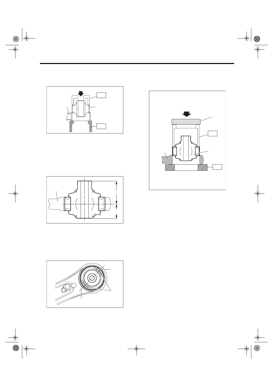
Front Arm
FRONT SUSPENSION
3) Using the ST and a press, install the rear bush-
ing.
ST1 20299AG000 REMOVER
ST2 20299AG010 BASE
Aluminum front arm
1) Install the pillow ball bushing with its longer inner
cylinder facing upward and the shorter facing
downward as shown in the figure.
2) Align the center of rear bushing recess portion
with the aligning mark on the front arm.
3) Using the ST and a press, install the rear bush-
ing.
ST1 20299AE020
INSTALLER & REMOVER
ST2 18723AA000
REMOVER ASSY (GEAR
DRIVEN)
NOTE:
Place the plate on the ST1 to use the press.
E: INSPECTION
1) Check the front arm for damage or cracks, and
correct or replace if defective.
2) Check the bushing for abnormal fatigue or dam-
age.
3) Check the pillow ball bushing for damage or
cracks, and replace if defective.
4) Try to wobble the pillow ball bushing. Replace
the pillow ball bushing if backlash or resistance are
found.
(1) Press
(2) Front arm
(3) Rear bushing
(1) Front arm
(2) Bushing inner cylinder
(3) Longer
(4) Shorter
(1) Alignment mark
(2) Recess section
FS-00127
(1)
(2)
(3)
ST2
ST1
FS-00441
(1)
(2)
(3)
(4)
FS-00440
(1)
(2)
(1)
(1) Press
(2) Front arm
(3) Rear bushing
(4) Plate
FS-00426
(1)
(2)
(3)
ST1
(4)
ST2