Subaru Impreza 3 / Impreza WRX / Impreza WRX STI. Manual - part 470
FS-15
Wheel Alignment
FRONT SUSPENSION
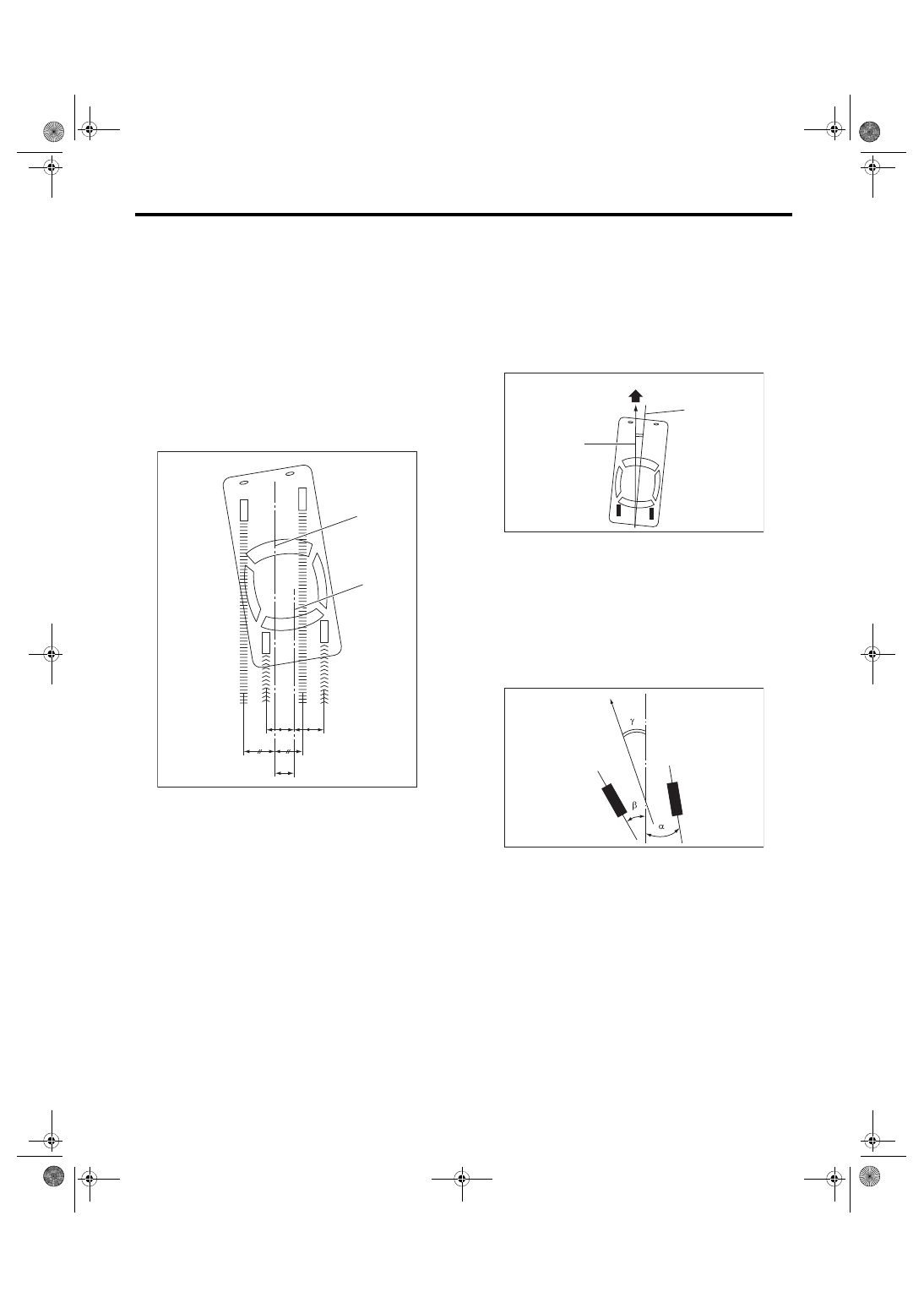
7. THRUST ANGLE
• Inspection
1) Park the vehicle on a level surface.
2) Move the vehicle 3 to 4 meters (10 to 13 feet)
straight forward.
3) Draw the center of loci for both the front and rear
axles.
4) Measure distance “L” between the center lines of
the axle loci.
Thrust angle
0°
±
30
′
Less than 30
′
when “L” is 23 mm (0.9 in) or
less
• Adjustment
When adjusting, adjust it to the following value.
Thrust angle
0°
±
20
′
Less than 20
′
when “L” is 15 mm (0.6 in) or
less
1) Make thrust angle adjustments by turning the
toe-in adjusting bolts of the rear suspension equally
in the same direction.
2) When one rear wheel is adjusted in a toe-in di-
rection, adjust the other rear wheel equally in toe-
out direction, in order to make the thrust angle ad-
justment.
3) When the left and right adjusting bolts are turned
by one graduation, the thrust angle will change ap-
prox. 15′ (“L” is approx. 11 mm (0.43 in)).
NOTE:
Thrust angle is a mean value of left and right wheel
toe angles in relation to the vehicle body center
line. Vehicle is driven straight in the thrust angle di-
rection while slanting in the oblique direction de-
pending on the degree of the mean thrust angle.
Thrust angle:
γ
= (
α
–
β
)/2
α: Rear RH wheel toe-in angle
β: Rear LH wheel toe-in angle
Substitute only the positive toe-in values from each
wheel into α and β in the calculation.
(1) Center line of loci (front axle)
(2) Center line of loci (rear axle)
(1)
(2)
L
FS-00022
(1) Front
(2) Thrust angle
(3) Body center line
(1) Front
(2) Body center line
FS-00024
(2)
(3)
(1)
FS-00976
(1)
(2)