Subaru Impreza 3 / Impreza WRX / Impreza WRX STI. Manual - part 471


  Index      Subaru     Subaru Impreza 3 / Impreza WRX / Impreza WRX STI - service repair manual 2008-2014 year


Search            


Content   ..  469  470  471  472   ..


Subaru Impreza 3 / Impreza WRX / Impreza WRX STI. Manual - part 471


FS-19

Front Ball Joint

FRONT SUSPENSION

C: INSPECTION

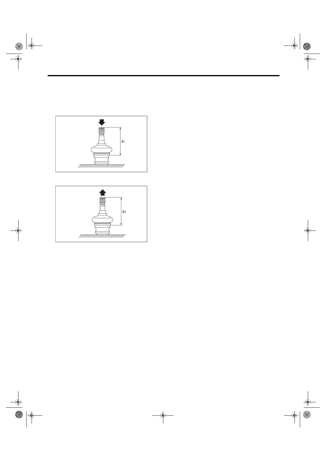
1) Measure the play of the ball joint using the fol-

lowing procedures. Replace with a new part if the

play exceeds specification.

(1) With 686 N (70 kgf, 154 lbf) loaded in direc-

tion shown in the figure, measure the length L

1

.

(2) With 686 N (70 kgf, 154 lbf) loaded in direc-

tion shown in the figure, measure the length L

2

.

(3) Determine free play using the following for-

mula.

S = L

2

 – L

1

(4) Replace with a new part if the play exceeds

specification.

Front ball joint

Specification for replacement S:

Less than 0.3 mm (0.012 in)

2) If the play is within specification, visually check

the dust cover.

3) Remove the ball joint and cover, and check for

wear, damage or cracks. If any damage is found,

replace the corresponding part.

4) If the dust cover is damaged, replace with a new

ball joint.

FS-00035

FS-00036

FS-20

Front Arm

FRONT SUSPENSION

6. Front Arm

A: REMOVAL

1) Lift  up  the  vehicle,  and  then  remove  the  front

wheels.

2) Remove  the  front  crossmember  support  plate.

<Ref.  to  FS-16,  REMOVAL,  Front  Crossmember

Support Plate.>

3) Remove the front stabilizer. <Ref. to FS-17, RE-

MOVAL, Front Stabilizer.>

4) Remove the ball joint of front arm.

5) Remove the nut securing the front arm to cross-

member. (Do not remove the bolt.)

6) Remove the front arm support plate.

7) Remove  the  bolt  securing  front  arm  to  cross-

member  and  pull  the  front  arm  out  of  the  cross-

member.

8) To remove the stud bolt, use the ST. (Except for

STI model)
CAUTION:

Do not remove the stud bolt unnecessarily. Al-

ways replace the parts with new parts when re-

moved.

ST 20299AG020 STUD BOLT SOCKET

B: INSTALLATION

1) Using  the  ST,  install  the  stud  bolt.  (Except  for

STI model)

ST 20299AG020 STUD BOLT SOCKET
Tightening torque:

110 N·m (11.2 kgf-m, 81.1 ft-lb)

2) Using new bolts and self-locking nuts, temporari-

ly tighten the front arm to crossmember.

3) Attach the support plate.

• Except for STI model

Secure the front arm to body, and then install the

support plate with new bolts and self-locking nuts.

• STI model

Secure the front arm to body, and then install the

support plate with new bolts.
Tightening torque:

Support plate to Front arm:

Except for STI model: 110 N·m (11.2 kgf-m, 

81.1 ft-lb)

STI model: 140 N·m (14.3 kgf-m, 103.3 ft-lb)

Support plate to Body:

150 N·m (15.3 kgf-m, 110.6 ft-lb)

FS-00106

FS-00107

FS-00108

(1) Vehicle body
(2) Stud bolt

FS-00279

(2)

(1)

ST

FS-21

Front Arm

FRONT SUSPENSION

4) Install the ball joint into housing.
Tightening torque:

50 N·m (5.1 kgf-m, 36.9 ft-lb)

5) Install the stabilizer. <Ref. to FS-17, INSTALLA-

TION, Front Stabilizer.>

6) Install the front wheels.

7) Lower the vehicle from lift, and tighten the bolt

which secures the front arm to crossmember with

wheels in full contact with the ground and the vehi-

cle at curb weight.
Tightening torque:

95 N·m (9.7 kgf-m, 70.1 ft-lb)

8) Inspect the wheel alignment and adjust if neces-

sary.

C: DISASSEMBLY

1. FRONT BUSHING

Using the ST and a press, remove the front bush-

ing.

ST 927680000

INSTALLER & REMOVER 

SET

2. REAR BUSHING

Steel front arm
1) Put an alignment mark on the front arm based on

the center of rear bushing recess portion.
CAUTION:

Always put an alignment mark for aligning the

position on bushing installation.

2) Using the ST and a press, remove the rear bush-

ing.

ST1 20299AG000 REMOVER

ST2 20299AG010 BASE

FS-00110

ST

(1) Put an alignment mark.
(2) Recess section

(1) Press
(2) Front arm
(3) Rear bushing

FS-00111

(1)

(2)

(1)

FS-00126

(1)

(2)

(3)

ST2

ST1

FS-22

Front Arm

FRONT SUSPENSION

Aluminum front arm
1) Put an alignment mark on the front arm based on

the center of pillow ball bushing recess portion.
CAUTION:

Always put an alignment mark for aligning the

position on bushing installation.

2) Using the ST and a press, remove the pillow ball

bushing.

ST1 20099AE020

INSTALLER & REMOVER

ST2 28099PA010

HOUSING STAND

NOTE:

Place the plate on the ST1 to use the press.

D: ASSEMBLY

1. FRONT BUSHING

Assemble each part in the reverse order of disas-

sembly.

2. REAR BUSHING

Steel front arm
1) Install the rear bushing with its longer inner cyl-

inder facing upward and the shorter facing down-

ward and protruding part rearward as shown in the

figure.

2) Align the center of rear bushing recess portion

with the aligning mark on the front arm.

(1) Put an alignment mark.
(2) Recess section

(1) Press
(2) Front arm
(3) Pillow ball bushing
(4) Plate

FS-00440

(1)

(2)

(1)

FS-00425

(1)

(2)

(3)

ST2

ST1

(4)

(1) Front arm
(2) Bushing inner cylinder
(3) Longer
(4) Shorter
(5) Protrusion portion

(1) Alignment mark
(2) Recess section

FS-00113

(2)

(1)

(3)

(4)

(5)

FS-00111

(1)

(2)

(1)


Content   ..  469  470  471  472   ..