Subaru Impreza 3 / Impreza WRX / Impreza WRX STI. Manual - part 473


  Index      Subaru     Subaru Impreza 3 / Impreza WRX / Impreza WRX STI - service repair manual 2008-2014 year


Search            


Content   ..  471  472  473  474   ..


Subaru Impreza 3 / Impreza WRX / Impreza WRX STI. Manual - part 473


FS-27

Front Crossmember

FRONT SUSPENSION

8. Front Crossmember

A: REMOVAL

1) Lift  up  the  vehicle,  and  then  remove  the  front

wheels.

2) Remove the front exhaust pipe.

3) Remove  the  front  crossmember  support  plate.

<Ref.  to  FS-16,  REMOVAL,  Front  Crossmember

Support Plate.>

4) Remove the front stabilizer. <Ref. to FS-17, RE-

MOVAL, Front Stabilizer.>

5) Disconnect the tie-rod ends from the housing.

6) Remove the front arm. <Ref. to FS-20, REMOV-

AL, Front Arm.>

7) Remove the nuts which install the engine mount-

ing cushion rubber onto the crossmember.

8) Remove the steering universal joint.

9) Disconnect  the  power  steering  hose  from  the

steering gearbox.

10) Lift the engine by approx. 10 mm (0.39 in) by

using the chain block.

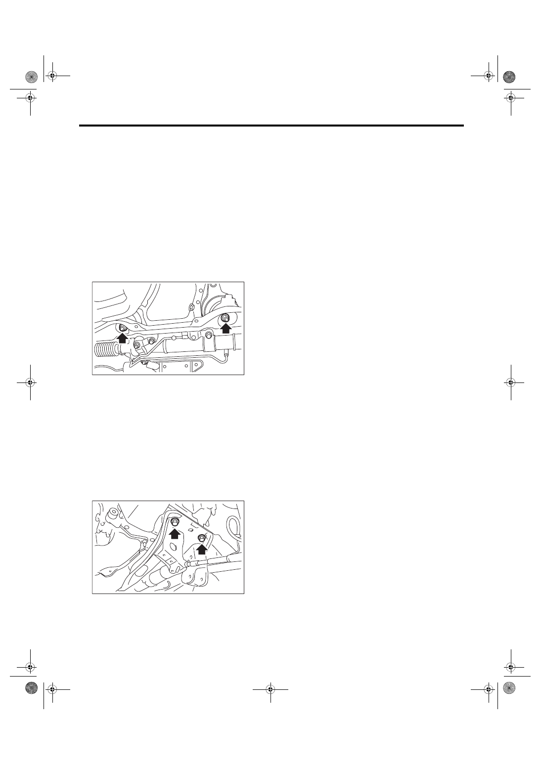
11) Support  the  crossmember  with  jack,  remove

the bolts which secure the crossmember to the ve-

hicle body, and gradually lower the crossmember

together with the steering gearbox.
CAUTION:

When  removing  the  crossmember  downward,

make sure that the tie-rod end does not inter-

fere with the drive shaft boot.

B: INSTALLATION

1) Install each part in the reverse order of removal.
CAUTION:

• Use a new bolt and self-locking nut. For parts

which are not reusable, refer to COMPONENT.

<Ref. to FS-3, COMPONENT, General Descrip-

tion.>

• Always tighten the bushing in the state where

the vehicle is at curb weight and the wheels are

in full contact with the ground.
Tightening torque:

Crossmember to Body:

95 N·m (9.7 kgf-m, 70.1 ft-lb)

Engine mounting to Crossmember:

45 N·m (4.6 kgf-m, 33.2 ft-lb)

Front arm to Crossmember:

95 N·m (9.7 kgf-m, 70.1 ft-lb)

Support plate to Front arm:

Except for STI model: 110 N·m (11.2 kgf-m, 

81.1 ft-lb)

STI model: 140 N·m (14.3 kgf-m, 103.3 ft-lb)

Front arm to Support plate (except for STI 

model):

110 N·m (11.2 kgf-m, 81.1 ft-lb)

Support plate body:

150 N·m (15.3 kgf-m, 110.6 ft-lb)

Tie-rod end to Housing:

27 N·m (2.8 kgf-m, 19.9 ft-lb)

After tightening to the specified torque, tighten the

castle nut further but within 60° until the hole in the

ball stud is aligned with a slot in castle nut.
Tightening torque:

Universal joint:

24 N·m (2.4 kgf-m, 17.7 ft-lb)

Stabilizer bracket:

25 N·m (2.5 kgf-m, 18.4 ft-lb)

Stabilizer link:

38 N·m (3.9 kgf-m, 28.0 ft-lb)

Power steering hose to Steering gearbox:

15 N·m (1.5 kgf-m, 11.1 ft-lb)

2) Purge air from the power steering system.

3) Inspect the wheel alignment and adjust if neces-

sary.

C: INSPECTION

Check the crossmember for damage or cracks, and

correct or replace if defective.

FS-00118

FS-00119

FS-28

General Diagnostic Table

FRONT SUSPENSION

9. General Diagnostic Table

A: INSPECTION

1. IMPROPER VEHICLE POSTURE OR IMPROPER WHEEL ARCH HEIGHT

2. POOR RIDE COMFORT

1) Large rebound shock

2) Rocking of the vehicle continues too long after running over bump and hump.

3) Excessive shock in bumping

3. NOISE

Possible cause

Corrective action

(1) Permanent distortion or damage of the coil spring

Replace.

(2) Rough operation of strut or shock absorber

Replace.

(3) Improper installation of strut or shock absorber

Replace with appropriate parts.

(4) Installation of the wrong coil spring

Replace with appropriate parts.

Possible cause

Corrective action

(1) Damaged coil spring

Replace.

(2) Overinflation of tires

Adjust.

(3) Improper wheel arch height

Replace the coil springs with new parts.

(4) Fault in operation of strut or shock absorber

Replace.

(5) Damage or deformation of strut mount or shock absorber mount

Replace.

(6) Unsuitable length (maximum or minimum) of strut or shock absorber

Replace with appropriate parts.

(7) Abnormal deformation or loss of bushing

Replace.

(8) Deformation or damage of helper in strut assembly or shock absorber

Replace.

(9) Oil leakage from the strut or shock absorber

Replace.

Possible cause

Corrective action

(1) Wear or damage of strut or shock absorber component parts

Replace.

(2) Loosening of the suspension link installing bolt

Tighten to the specified torque.

(3) Abnormal deformation or loss of bushing

Replace.

(4) Unsuitable length (maximum or minimum) of strut or shock absorber

Replace with appropriate parts.

(5) Damaged coil spring

Replace.

(6) Wear or damage of the ball joint

Replace.

(7) Deformation of the stabilizer clamp

Replace.

RS-2

General Description

REAR SUSPENSION

1. General Description

A: SPECIFICATION

Refer to “FS” section for rear suspension specifica-

tions.  <Ref.  to  FS-2,  SPECIFICATION,  General

Description.>
NOTE:

• Front  and  rear  toe-in  and  front  camber  can  be

adjusted. Adjust if the toe-in or camber tolerance

exceeds specifications.

• Other items indicated in the specifications is not

equipped  with  adjustment  mechanisms.  If  other

items exceed specifications, check the suspension

parts and connections for deformation. If defective,

replace with new parts.

(1) Front


A – B = Positive: Toe-in, Negative: Toe-out

α = Individual toe angles

B

A

(1)

FS-00269


Content   ..  471  472  473  474   ..