Subaru Impreza 3 / Impreza WRX / Impreza WRX STI. Manual - part 464
 

  Index      Subaru     Subaru Impreza 3 / Impreza WRX / Impreza WRX STI - service repair manual 2008-2014 year


Search            


Content   ..  462  463  464  465   ..


Subaru Impreza 3 / Impreza WRX / Impreza WRX STI. Manual - part 464


CL-31

Clutch Pedal

CLUTCH SYSTEM

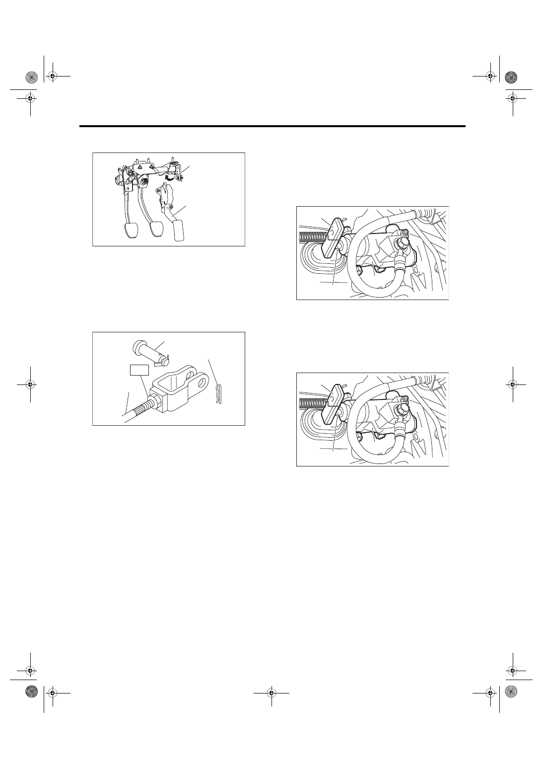
7) Turn further in the direction that will shorten the

push rod (arrow direction shown in figure) by 270°.

8) Check  that  the  clevis  pin  moves  smoothly  by

moving it in the left and right directions.

9) Tighten the push rod lock nut.
Tightening torque (Push rod lock nut):

T: 10 N·m (1.0 kgf-m, 7.4 ft-lb)

10) Depress  and  release  the  clutch  pedal  two  or

three times to ensure that the clutch pedal and re-

lease  lever  operate  smoothly.  If  the  clutch  pedal

and release lever do not operate smoothly, bleed

air from the clutch hydraulic system. <Ref. to CL-

26, Clutch Fluid Air Bleeding.>

11) Measure  the  clutch  pedal  full  stroke  length

again to ensure that it is within specifications. If it is

not within specifications, repeat adjustment proce-

dures again from the beginning.
Clutch pedal full stroke:

STI model

130 — 135 mm (5.12 — 5.31 in)

Except for STI model

135 — 140 mm (5.31 — 5.51 in)

12) Push the release lever until the operating cylin-

der push rod retracts. Make sure that the clutch flu-

id level in the reservoir tank increases. If the clutch

fluid level increases, the hydraulic clutch is properly

adjusted. If the fluid level does not increase or the

push rod does not retract, replace the master cylin-

der with a new part. <Ref. to CL-22, Master Cylin-

der.>

13) Push the release lever until the operating cylin-

der  push  rod  retracts.  Check  that  the  clutch  fluid

level in the reservoir tank increases.

14) If  the  clutch  fluid  level  increases,  hydraulic

clutch play is correct.

15) If  the  clutch  fluid  level  does  not  increase  or

push rod does not retract, readjust the clutch pedal.

(A) Accelerator pedal
(B) Clevis

(A) Clevis pin
(B) Snap pin

(C) Push rod

CL-00600

(B)

(A)

CL-00226

(A)

(B)

(C)

T

(A) Push rod
(B) Release lever

(C) Operating cylinder

(A) Push rod
(B) Release lever

(C) Operating cylinder

CL-00663

(A)

(B)

(C)

CL-00663

(A)

(B)

(C)

CL-32

Clutch Pedal

CLUTCH SYSTEM

16) Check the fluid level using the scale on the out-

side of the reservoir tank. If the level is below “MIN”,

fill fluid up to “MAX” level.
Recommended clutch fluid:

New FMVSS No. 116 DOT3 or DOT4

(A) Reservoir tank
(B) MIN. level

(C) MAX. level

MIN 

MAX 

( A )

( C )

( B )

CL-00567

CL-33

Clutch Switch

CLUTCH SYSTEM

11.Clutch Switch

A: REMOVAL

1) Disconnect the ground cable from battery.

2) Remove the instrument panel lower cover.

3) Disconnect the connector from the clutch switch.

4) Remove the clutch switches.

B: INSTALLATION

1. CLUTCH SWITCH (CRUISE CONTROL)

1) Move the clevis pin of push rod to left and right,

retain  it  at  the  position  where  it  moves  smoothly,

and measure the clutch pedal stroke.
Clutch pedal full stroke A:

STI model

130 — 135 mm (5.12 — 5.31 in)

Except for STI model

135 — 140 mm (5.31 — 5.51 in)

Tightening torque:

T: 8 N·m (0.8 kgf-m, 5.9 ft-lb)

2) If the clutch pedal stroke is out of specification,

adjust the stroke. <Ref. to CL-30, ADJUSTMENT,

Clutch Pedal.>

3) Connect the clutch switch connector.

2. CLUTCH START SWITCH

1) Fully depress the clutch pedal and hold it.

2) Install the clutch pedal plate and clutch switch so

that the gap between them is 1.1 — 2.1 mm (0.04

— 0.08 in), and then tighten the lock nut.
Tightening torque:

8 N·m (0.8 kgf-m, 5.9 ft-lb)

3) Connect the clutch switch connector.

4) Make sure that engine does not start with clutch

pedal not depressed.

5) Make  sure  that  engine  starts  with  clutch  pedal

fully depressed.

CL-00225

T

A

(A) Plate
(B) Clutch start switch

(C) 1.1 — 2.1 mm (0.04 — 0.08 in)

(A)

(B)

(C)

CL-00104

CL-34

Clutch Switch

CLUTCH SYSTEM

C: INSPECTION

1. CLUTCH START SWITCH

1) Perform  the  following  inspections.  If  the  clutch

start switch does not operate normally, adjust the

switch,  and  check  it  again.  <Ref.  to  CL-35,  AD-

JUSTMENT, Clutch Switch.>

• Make sure that engine does not start with clutch

pedal not depressed.

• Make  sure  that  engine  starts  with  clutch  pedal

fully depressed.

2) When  the  clutch  start  switch  does  not  operate

normally even if it is adjusted, check the clutch start

switch for continuity.

(1) Remove the clutch start switch. <Ref. to CL-

33, REMOVAL, Clutch Switch.>

(2) Measure the resistance between terminal 1

and 2 of the switch. If the resistance is not at the

standard value, replace the switch.

(3) Check that the switch is turned on and off in

Dimension L.

Dimension L:

4 — 5.5 mm (0.16 — 0.22 in)

2. CLUTCH SWITCH

1) Check the clutch switch for continuity.

(1) Disconnect the connector of clutch switch.

(2) Measure the resistance between terminal 1

and 2 of the switch. If the resistance is not within

the specification, check the clutch stroke and in-

stallation condition, and check the clutch switch

again.

2) When  the  clutch  switch  does  not  operate  nor-

mally even if the clutch stroke and installation con-

dition  are  normal,  check  the  clutch  switch  for

continuity.

(1) Remove  the  clutch  switches.  <Ref.  to  CL-

33, REMOVAL, Clutch Switch.>

(2) Measure the resistance between terminal 1

and 2 of the switch. If the resistance is not at the

standard value, replace the switch.

Condition

Terminal No.

Specified 

resistance

ON

No. 1 — No. 2

Less than 1 Ω

OFF

No. 1 — No. 2

1 MΩ or more

(A) ON
(B) OFF

CL-00102

1
2

CL-00799

L

(B)

(A)

Condition

Terminal No.

Specified 

resistance

When clutch pedal is 
depressed

No. 1 — No. 2

1 MΩ or more

When the clutch pedal 
is not depressed

No. 1 — No. 2

Less than 1 Ω

Condition

Terminal No.

Specified 

resistance

ON

No. 1 — No. 2

Less than 1 Ω

OFF

No. 1 — No. 2

1 MΩ or more

CL-00084

2 1

CL-00084

2 1


Content   ..  462  463  464  465   ..