Subaru Impreza 3 / Impreza WRX / Impreza WRX STI. Manual - part 463


  Index      Subaru     Subaru Impreza 3 / Impreza WRX / Impreza WRX STI - service repair manual 2008-2014 year


Search            


Content   ..  461  462  463  464   ..


Subaru Impreza 3 / Impreza WRX / Impreza WRX STI. Manual - part 463


CL-27

Clutch Fluid Air Bleeding

CLUTCH SYSTEM

2. EXCEPT FOR STI MODEL

NOTE:

Bleed air from the oil line with help of a co-worker.

1) Remove the intercooler. <Ref. to IN(w/o STI)-12,

REMOVAL, Intercooler.>

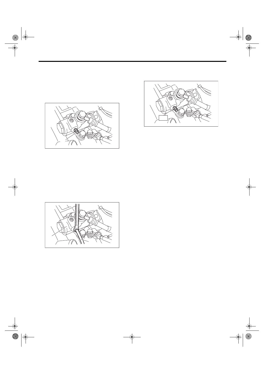
2) Fit one end of a vinyl tube into the air breather of

the operating cylinder, and put the other end into a

clutch fluid container.

3) Slowly  depress  the  clutch  pedal  several  times

and keep it depressed. Open the air breather to dis-

charge  air  together  with  the  clutch  fluid.  Release

the air breather for 1 or 2 seconds. Next, close the

air breather, and slowly release the clutch pedal.
CAUTION:

Cover  the  air  breather  with  cloth  to  prevent

clutch fluid from being splashed on surround-

ing parts when loosening the breather.

4) Repeat procedure 3), until there are no more air

bubbles appearing from the air breather.

5) Tighten the air breather.
Tightening torque:

T: 7.8 N·m (0.8 kgf-m, 5.8 ft-lb)

6) After  stepping  on  the  clutch  pedal,  make  sure

that there are no leaks evident in the entire clutch

system.

7) After bleeding the air from clutch system, ensure

that the clutch operates properly.

8) Install  the  intercooler.  <Ref.  to  IN(w/o  STI)-12,

INSTALLATION, Intercooler.>

(A) Air breather

(A) Operating cylinder
(B) Vinyl tube

CL-00777

(A)

CL-00711

(B)

(A)

CL-00712

T

CL-28

Clutch Pedal

CLUTCH SYSTEM

10.Clutch Pedal

A: REMOVAL

1) Disconnect the ground cable from battery.

2) Remove  the  steering  column.  <Ref.  to  PS-16,

REMOVAL, Steering Column.>

3) Disconnect  the  connector  from  the  stop  light

switch and clutch switch.

4) Remove the snap pins from clevis pins which se-

cure the lever to the push rod and operating rod.

5) Pull out the clevis pins which secures the lever to

the push rod and operating rod.

6) Remove the intercooler.

<Ref.  to  IN(STI)-12,  REMOVAL,  Intercooler.>

<Ref. to IN(w/o STI)-12, REMOVAL, Intercooler.>

7) Remove the nut which secures the clutch master

cylinder.

8) Remove  the  bolts  and  nuts  which  secure  the

brake pedal and clutch pedal, and remove the ped-

al assembly.

B: INSTALLATION

1) Install in the reverse order of removal.
CAUTION:

Always use a new clevis pin.

2) Adjust the clutch pedal after installation. <Ref. to

CL-30, ADJUSTMENT, Clutch Pedal.>

3) Adjust  the  clutch  start  switch.  <Ref.  to  CL-35,

ADJUSTMENT, Clutch Switch.>

C: DISASSEMBLY

1) Remove the clutch switches.

2) Remove the clip, assist spring, rod and bushing.

3) Remove the spring pin and lever.

(A) Operating rod
(B) Push rod

(C) Snap pin
(D) Clevis pin

CL-00090

(B)

(C)

(D)

(D)

(C)

(A)

CL-00093

(A) Clip
(B) Assist spring

(C) Assist rod A
(D) Assist rod B

(E) Assist bushing

(F) Clutch clevis pin

(G) Bushing

(A) Spring pin
(B) Lever

CL-00692

(A)

(B)

(C)

(D)

(G)

(E)

(F)

CL-00095

(A)

(B)

CL-29

Clutch Pedal

CLUTCH SYSTEM

4) Remove the clutch pedal and bushings.

5) Remove the stopper and clutch pedal pad from

the clutch pedal.

6) Remove the stopper from the clutch pedal brack-

et.

D: ASSEMBLY

1) Attach the stopper and clutch pedal pad to the

clutch pedal.

2) Install the clutch switch to the pedal bracket.

3) Clean the pedal bushing holes of the clutch ped-

al and the brake pedal, apply grease, and install the

pedal bushings.

4) Install the clutch pedal, brake pedal and lever to

the pedal bracket, and fix with a spring pin.

5) Install the assist rod A, assist rod B, assist bush-

ing and assist spring to the clutch pedal and pedal

bracket.

E: INSPECTION

Move the clutch pedal pads in the lateral direction

with a force of approximately 10 N (1 kgf, 2 lbf) to

check that the clutch pedal deflection is within the

service limit.
CAUTION:

If the play exceeds the service limit, replace the

bushing with a new part.
Deflection of the clutch pedal:

Service limit

4.0 mm (0.157 in) or less

(A) Clutch pedal
(B) Bushing

(A) Stopper
(B) Clutch pedal pad

(A) Stopper

CL-00602

(B)

(A)

(B)

CL-00670

(A)

(B)

CL-00603

(A)

(A) Clutch pedal
(B) Brake pedal

CL-00098

(A)

(B)

CL-30

Clutch Pedal

CLUTCH SYSTEM

F: ADJUSTMENT

1) Turn  the  lock  nut  until  the  full  stroke  of  clutch

pedal becomes within the specification.
CAUTION:

When adjusting the full stroke of clutch pedal,

do not turn the clutch switch.
NOTE:

If the lock nut cannot adjust the full stroke of clutch

pedal to the specified value, adjust it by turning the

master cylinder push rod.
Clutch pedal full stroke A:

STI model

130 — 135 mm (5.12 — 5.31 in)

Except for STI model

135 — 140 mm (5.31 — 5.51 in)

Tightening torque (Clutch switch lock nut):

T: 8 N·m (0.8 kgf-m, 5.9 ft-lb)

2) If the full stroke is not within the specified value,

loosen the clutch switch lock nut to adjust.
Tightening torque:

8 N·m (0.8 kgf-m, 5.9 ft-lb)

3) Loosen the push rod lock nuts.

4) Rotate the push rod to adjust.

(1) Make sure that the clutch pedal contacts the

clutch switch side when the pedal is released.

(2) Make sure that the clutch pedal contacts the

clutch  pedal  bracket  stopper  when  the  clutch

pedal is at the maximum stroke position.

5) Turn the push rod to shorten until a clearance is

gained on the clutch switch side.

6) Turn the push rod to lengthen until clutch pedal

contacts the clutch switch.

(A) Clevis pin
(B) Snap pin

(C) Push rod
(D) Push rod lock nut

CL-00225

T

A

CL-00042

(A)

(B)

(C)

(D)

(A) Clevis hole
(B) Push rod lock nut

(C) In the shorter direction
(D) In the longer direction

(E) Push rod

(F) Clevis

(A) Clutch switch
(B) Stopper

CL-00080

(B)

(A)

(C)

(D)

(E)

(F)

CL-00605

(A)

(B)


Content   ..  461  462  463  464   ..