Subaru Impreza 3 / Impreza WRX / Impreza WRX STI. Manual - part 462
CL-23
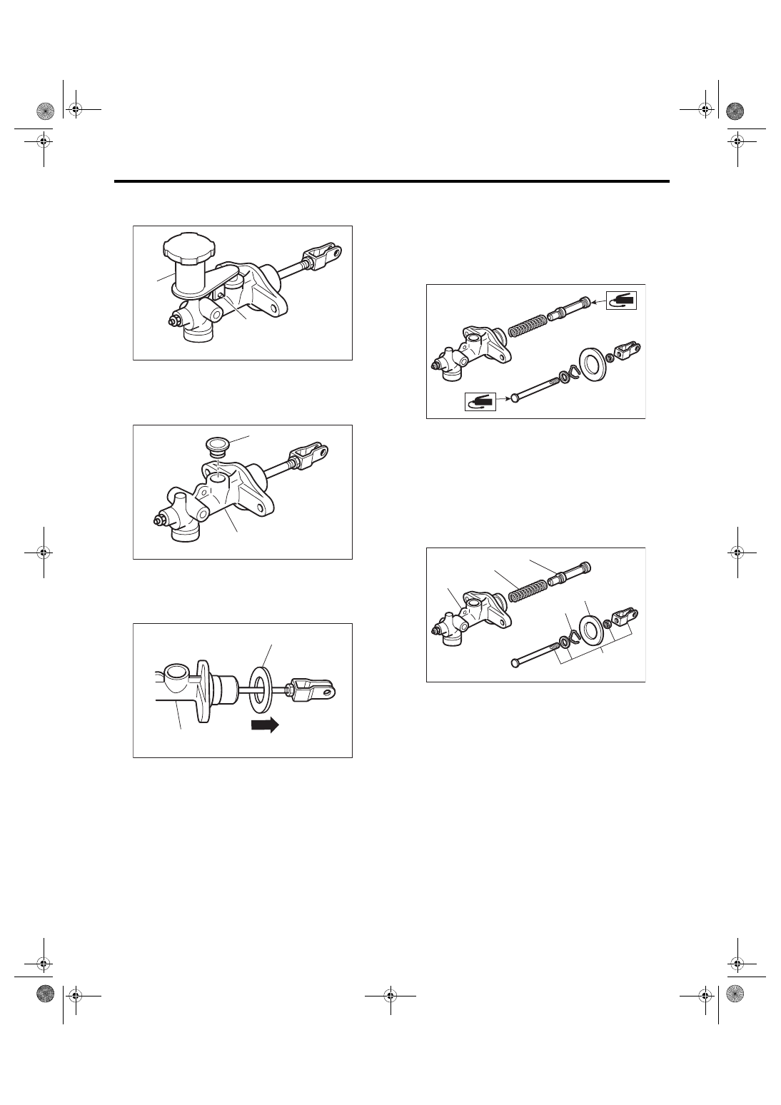
Master Cylinder
CLUTCH SYSTEM
C: DISASSEMBLY
1) Remove the straight pin and reservoir tank.
2) Remove the oil seal.
3) Move the seat towards the rear.
4) Remove the piston stop ring.
CAUTION:
When removing the piston stop ring, be careful
to prevent the rod, washer, piston and return
spring from popping out.
D: ASSEMBLY
1) Apply a coat of grease to the contact surfaces of
the push rod and piston before installation.
Grease:
SILICONE GREASE G-40M (Part No.
004404003) or equivalent
2) Assemble in the reverse order of disassembly.
Tightening torque:
10 N·m (1.0 kgf-m, 7.4 ft-lb)
E: INSPECTION
If any damage, deformation, wear, swelling, rust or
other faults are found on the cylinder, piston, push
rod, reservoir tank, return spring, breather screw,
seat or hose, replace the faulty part.
(A) Reservoir tank
(B) Straight pin
(A) Oil seal
(B) Master cylinder
(A) Seat
(B) Master cylinder
CL-00631
(A)
(B)
CL-00632
(A)
(B)
CL-00513
(A)
(B)
(A) Master cylinder body
(B) Return spring
(C) Piston
(D) Piston stop ring
(E) Push rod ASSY
(F) Seat
CL-00633
CL-00634
(B)
(C)
(D)
(E)
(A)
(F)