Subaru Impreza 3 / Impreza WRX / Impreza WRX STI. Manual - part 434
 

  Index      Subaru     Subaru Impreza 3 / Impreza WRX / Impreza WRX STI - service repair manual 2008-2014 year


Search            


Content   ..  432  433  434  435   ..


Subaru Impreza 3 / Impreza WRX / Impreza WRX STI. Manual - part 434


6MT-73

Main Shaft Assembly

MANUAL TRANSMISSION AND DIFFERENTIAL

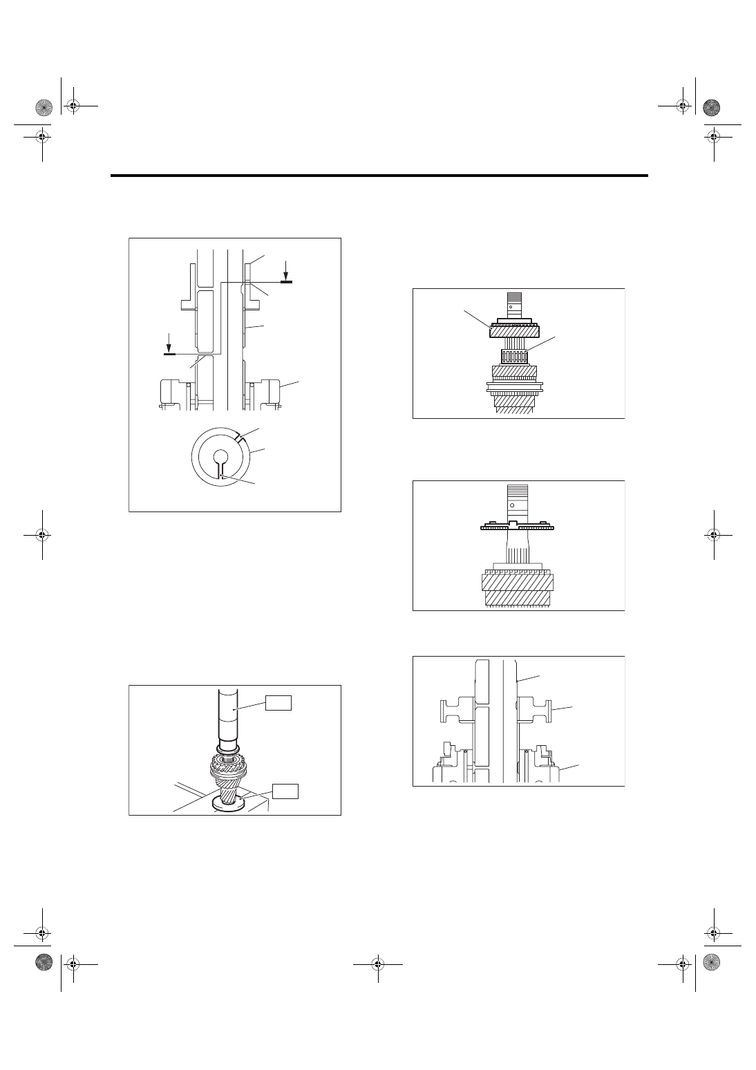
11) Install the 5th bushing.

(1) With the main shaft oil hole and 5th bushing

oil  hole  out  of  alignment,  attach  to  the  main

shaft.

(2) Using the ST, push into the 5th bushing.

ST1 18651AA000

INSTALLER

ST2 398177700

INSTALLER

CAUTION:

Do not apply pressure in excess of 40 kN (4.0

ton, 4.4 US ton, 3.9 Imp ton).

12) Make sure that the 4th drive gear can be turned

smoothly by hand. If it does not turn smoothly, re-

assemble.

13) Apply  adequate  transmission  gear  oil  to  the

main shaft, 5th needle bearing and 5th drive gear

inner surface.

14) Install  the  5th  needle  bearing  and  5th  drive

gear.

15) Install the 5th baulk ring.

16) Install the 5th-6th hub.

(1) Being  careful  of  the  install  direction  of  the

5th-6th hub, set to the main shaft.

(A) 5th bushing
(B) Main shaft oil hole

(C) Main shaft
(D) 5th bushing oil hole

(E) 4th drive gear

MT-01821

(A)

A

(D)

(C)

(E)

(B)

A

(D)

(A)

A - A

(B)

MT-00567

ST1

ST2

(A) 5th needle bearing
(B) 5th drive gear

(A) Main shaft
(B) 5th-6th hub

(C) 5th drive gear

MT-00568

(A)

(B)

MT-00569

MT-00570

(A)

(B)

(C)

6MT-74

Main Shaft Assembly

MANUAL TRANSMISSION AND DIFFERENTIAL

(2) Using the ST, push into the 5th-6th hub.

ST1 18651AA000

INSTALLER

ST2 398177700

INSTALLER

CAUTION:

Do not apply pressure in excess of 40 kN (4.0

ton, 4.4 US ton, 3.9 Imp ton).
NOTE:

When pushing into the 5th-6th hub, move the outer

baulk ring to match the protrusion of the outer baulk

ring and the cut out on the 5th-6th bushing.

17) Make sure that the 5th drive gear can be turned

smoothly by hand. If it does not turn smoothly, re-

assemble.

18) Attach the 5th-6th shifting insert key at the ap-

propriate position of the 5th-6th sleeve.
NOTE:

• The location angle of each shifting insert key is

120°.

• Refer to the following figure to install the shifting

insert key.

19) Attach the 5th-6th sleeve to the 5th-6th hub.
NOTE:

• There are two identification grooves on the 5th-

6th sleeve.

• Place  the  grooves  towards  the  5th  drive  gear,

and attach the 5th-6th sleeve.

(A) 5th-6th hub
(B) Outer baulk ring

(C) Cut out on the 5th-6th hub
(D) Protrusion of the outer baulk ring

MT-00571

(D)

(C)

(B)

(A)

(A)

ST1

ST2

(A) Attach the straight part of the shifting insert key 

to the sleeve convex portion.

(B) 5th-6th shifting insert key

(C) 5th-6th sleeve

(A) 5th drive gear
(B) 5th-6th sleeve identification groove (2)

(B)

(C)

MT-01820

(A)

(B)

(A)

MT-00572

(A)

(B)

6MT-75

Main Shaft Assembly

MANUAL TRANSMISSION AND DIFFERENTIAL

20) Install the 6th baulk ring.

21) Apply  adequate  transmission  gear  oil  to  the

main shaft, 6th needle bearing and 6th drive gear

inner surface.

22) Install the 6th drive gear.

23) Install the 6th needle bearing.

24) With 6th bushing oil hole and the main shaft oil

hole out of alignment, attach to the main shaft.

25) Using the ST, install the 6th bushing.

ST1 18651AA000

INSTALLER

ST2 398177700

INSTALLER

CAUTION:

Do not apply pressure in excess of 40 kN (4.0

ton, 4.4 US ton, 3.9 Imp ton).

26) Make sure that the 6th drive gear can be turned

smoothly by hand. If it does not turn smoothly, re-

assemble.

27) Using  the  ST,  install  the  inner  bearing  of  the

double taper roller bearing.

ST1 18651AA000

INSTALLER

ST2 398177700

INSTALLER

CAUTION:

Do not apply pressure in excess of 40 kN (4.0

ton, 4.4 US ton, 3.9 Imp ton).
NOTE:

Use a new double taper roller bearing.

(A) 6th bushing oil hole
(B) Main shaft oil hole

MT-00573

MT-00574

MT-00575

MT-01933

(B)

(A)

MT-00577

ST1

ST2

MT-00578

ST1

ST2

6MT-76

Main Shaft Assembly

MANUAL TRANSMISSION AND DIFFERENTIAL

28) Using the ST, install the outer race and the out-

er bearing of the double taper roller bearing.

ST1 18651AA000

INSTALLER

ST2 398177700

INSTALLER

CAUTION:

Do not apply pressure in excess of 40 kN (4.0

ton, 4.4 US ton, 3.9 Imp ton).
NOTE:

• Confirm  that  the  outer  race  is  installed  in  the

proper direction.

• Push  in  until  there  is  no  backlash  on  the  outer

race and the bearing turns smoothly by hand.

29) Make sure that the double taper roller bearing

turns smoothly by hand. If it does not turn smoothly,

replace the double taper roller bearing as a set, and

reassemble.

30) Attach a new lock washer and a new lock nut.

31) Set  the  main  shaft  assembly  to  the  ST,  and

tighten the lock nut.

ST1 18665AA000

HOLDER

ST2 18664AA000

BASE

NOTE:

Make sure the lock washer is installed in the proper

direction.
Tightening torque:

392 N·m (40.0 kgf-m, 289.1 ft-lb)

(A) Outer race
(B) Outer bearing of the double taper roller bearing

MT-00579

(B)

(A)

(A)

ST2

ST1

(A) Lock washer
(B) Lock nut

(C) Nut side

MT-02714

ST2

ST1

(B)

(A)

(C)


Content   ..  432  433  434  435   ..