Subaru Impreza 3 / Impreza WRX / Impreza WRX STI. Manual - part 435
6MT-77
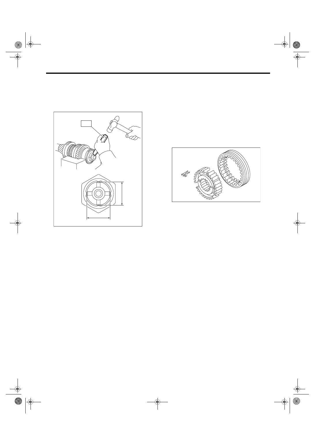
Main Shaft Assembly
MANUAL TRANSMISSION AND DIFFERENTIAL
32) Using the ST, crimp the lock nut in 4 locations,
with dimensions within A 27±0.3 mm (1.06±0.01
in).
ST 18668AA000 PUNCH
NOTE:
Do not damage the crimp area of the lock nut.
E: INSPECTION
Disassembled parts should be washed with clean-
ing solvent first, then inspected carefully.
1) Bearing
Replace the bearings in the following cases.
• Wear, rusting or damage of the bearings
• The bearing does not rotate smoothly or an ab-
normal noise is emitted when turning.
• The bearing has other defects.
2) Bushing (each gear)
Replace the bushing in following cases.
• The sliding surface is damaged or abnormally
worn.
3) Gear
Replace gears in the following cases.
• The gear teeth surface is damaged or excessive-
ly worn.
• The contact area of the baulk ring is damaged.
• The inner face of the gear is worn.
4) Baulk ring, synchro cone
Replace the baulk ring and synchro cone in the fol-
lowing cases.
• Wear, rusting or damage of the baulk ring
5) Shifting insert key
Replace the shifting insert key if deformed, exces-
sively worn or defective in any way.
F: ADJUSTMENT
1. MAIN SHAFT SNAP RING & ADJUSTING
WASHER SELECTION
NOTE:
In the following conditions, perform the procedures
below.
• 1st to 6th driven gear replacement
• 1st and 2nd synchro ring assembly replacement
• Ball bearing replacement
• Adapter plate replacement
• Driven shaft replacement
1) Insert the drive pinion assembly into the adapter
plate.
NOTE:
Confirm that the thrust bearing outer race has not
been removed and the drive pinion is not lifted.
MT-00580
A
A
ST
MT-00581