Subaru Impreza 3 / Impreza WRX / Impreza WRX STI. Manual - part 432


  Index      Subaru     Subaru Impreza 3 / Impreza WRX / Impreza WRX STI - service repair manual 2008-2014 year


Search            


Content   ..  430  431  432  433   ..


Subaru Impreza 3 / Impreza WRX / Impreza WRX STI. Manual - part 432


6MT-65

Main Shaft Assembly

MANUAL TRANSMISSION AND DIFFERENTIAL

17.Main Shaft Assembly

A: REMOVAL

1) Remove  the  manual  transmission  assembly

from  the  vehicle.  <Ref.  to  6MT-31,  REMOVAL,

Manual Transmission Assembly.>

2) Prepare the transmission for overhaul. <Ref. to

6MT-37, Preparation for Overhaul.>

3) Remove  the  neutral  position  switch,  back-up

light  switch  and  harness.  <Ref.  to  6MT-41,  RE-

MOVAL, Neutral  Position Switch.>  <Ref.  to  6MT-

39, REMOVAL, Back-up Light Switch.>

4) Remove  the  extension  case.  <Ref.  to  6MT-43,

REMOVAL, Extension Case.>

5) Remove the transfer driven gear. <Ref. to 6MT-

55, REMOVAL, Transfer Driven Gear.>

6) Remove the center differential. <Ref. to 6MT-57,

REMOVAL, Center Differential.>

7) Remove  the  transmission  case.  <Ref.  to  6MT-

58, REMOVAL, Transmission Case.>

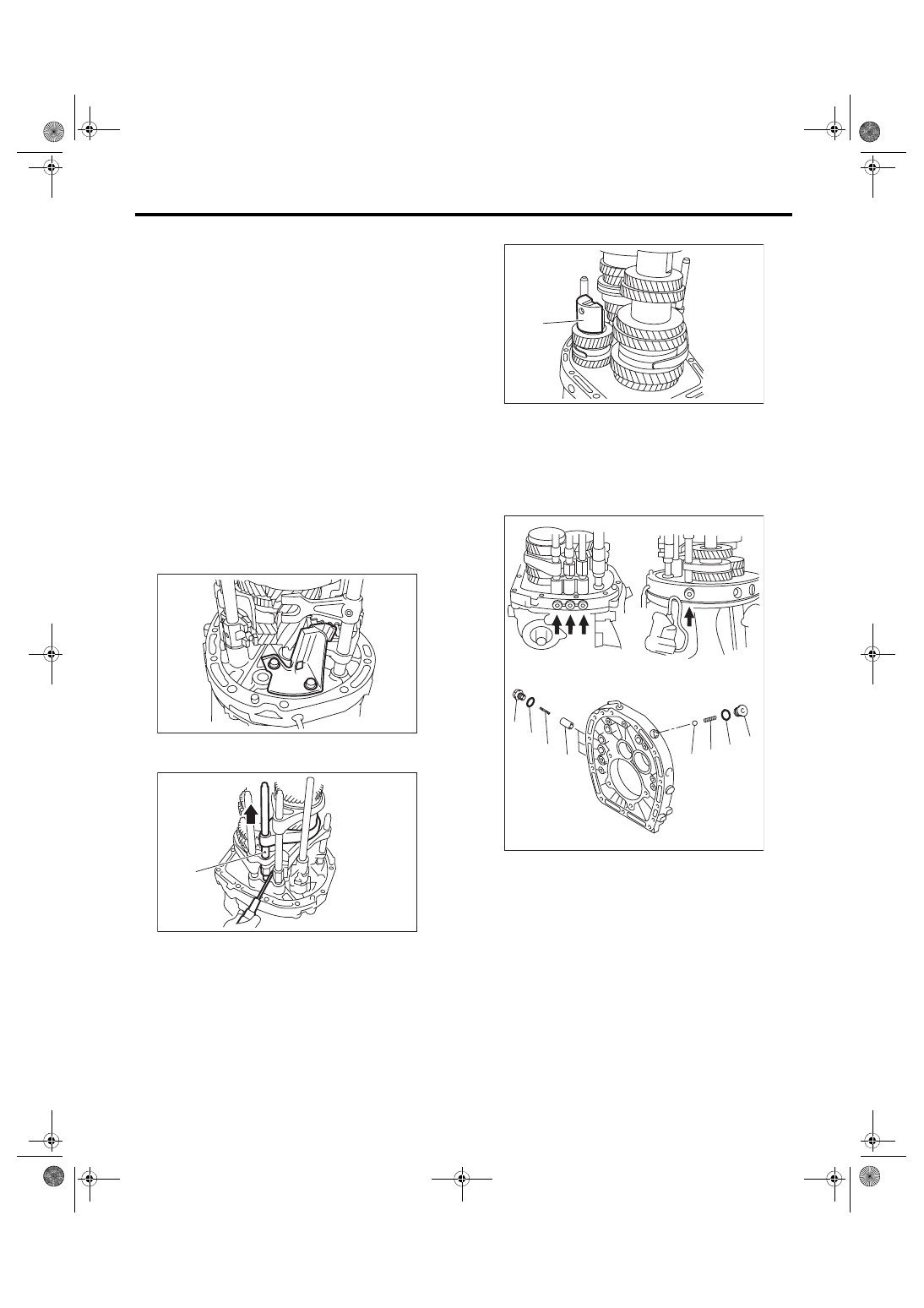
8) Remove the striking rod.

9) Remove the oil guide B.

10) Use a screwdriver to shift to the 4th gear posi-

tion.

11) Remove the reverse idler holder.

12) Remove the check plug, O-ring, check spring,

plunger and check ball from the adapter plate.
NOTE:

Do not reuse the O-ring.

(A) 3rd-4th shift rod

MT-01623

MT-01736

(A)

(A) Reverse idler holder

(A) Check plug
(B) O-ring

(C) Checking spring
(D) Plunger

(E) Check ball

MT-00544

(A)

(D)

(E)

(A)

(A)

(B)

(B)

(C)

(C)

MT-01931

6MT-66

Main Shaft Assembly

MANUAL TRANSMISSION AND DIFFERENTIAL

13) Remove  the  bolt  and  gasket  holding  the  re-

verse idler shaft.

14) Push the main shaft assembly, driven gear as-

sembly, reverse idler gear and shifter forks to re-

move from the adapter plate all at once.
NOTE:

A helper is required to perform this work.

B: INSTALLATION

1) Adjust the 3rd-4th and 5th-6th shifter fork rods.

<Ref.  to  6MT-112,  ADJUSTMENT,  Shifter  Fork

and Rod.>

2) Turn the sub gear counterclockwise for approxi-

mately  3  teeth.  Match  the  sub  gear  and  reverse

idler gear holes, and insert the ST.

ST 18757AA000 STRAIGHT PIN

3) Attach the driven gear assembly to the 1st-2nd

shifter fork assembly.

4) Attach  the  main  shaft  assembly  to  the  3rd-4th

shifter  fork,  and  assemble  to  the  driven  gear  as-

sembly.

(A) Sub gear
(B) Reverse idler gear

MT-00546

MT-00547

(A)

(B)

ST

(A) 1st-2nd shifter fork
(B) Driven gear ASSY

(C) 1st-2nd sleeve

(A) 3rd-4th shifter fork
(B) 3rd-4th sleeve

(C) Driven gear ASSY
(D) Main shaft ASSY

MT-00548

(A)

(B)

(C)

MT-00549

(C)

(A)

(B)

(C)

(D)

(D)

(A)

(B)

6MT-67

Main Shaft Assembly

MANUAL TRANSMISSION AND DIFFERENTIAL

5) Attach  the  5th-6th  shifter  fork  assembly  to  the

main shaft assembly.

6) Attach the reverse shifter fork assembly to the

reverse idler gear assembly.

7) Install the reverse idler gear assembly.

8) Install the thrust bearing of the driven gear as-

sembly.

9) Push on the shifter forks, main shaft assembly,

driven  gear  assembly  and  reverse  idler  gear  as-

semblies, to attach to the adapter plate all at once.
NOTE:

A helper is required to perform this work.

10) Install  the  plunger,  check  spring,  new  O-ring

and check plugs.
Tightening torque:

25 N·m (2.5 kgf-m, 18.4 ft-lb)

(A) 5th-6th shifter fork
(B) 5th-6th sleeve

(C) Main shaft ASSY

(A) Reverse idler gear ASSY
(B) Reverse shifter fork

(C) Reverse sleeve

(A) Reverse idler gear ASSY
(B) 1st drive gear

(C) Reverse gear

MT-00550

(B)

(A)

(C)

MT-00551

(A)

(B)

(C)

MT-00552

(B)

(A)

(C)

(A) Check plug
(B) O-ring

(C) Checking spring
(D) Plunger

MT-01932

(D)

(A)

(B)

(C)

6MT-68

Main Shaft Assembly

MANUAL TRANSMISSION AND DIFFERENTIAL

11) Install the check ball, check spring, new O-ring

and check plugs.
Tightening torque:

25 N·m (2.5 kgf-m, 18.4 ft-lb)

12) Attach the bolt and a new gasket.
Tightening torque:

25 N·m (2.5 kgf-m, 18.4 ft-lb)

13) Use a screwdriver to shift to the 4th gear posi-

tion.

14) Install the reverse idler holder.

15) Install the oil guide B.
Tightening torque:

18 N·m (1.8 kgf-m, 13.3 ft-lb)

16) Install the striking rod.

17) Install the transmission case. <Ref. to 6MT-60,

INSTALLATION, Transmission Case.>

18) Install  the  selected  main  shaft  snap  ring  and

washers.

19) Install the center differential. <Ref. to 6MT-57,

INSTALLATION, Center Differential.>

20) Install the transfer driven gear. <Ref. to 6MT-

55, INSTALLATION, Transfer Driven Gear.>

21) Install the extension case. <Ref. to 6MT-43, IN-

STALLATION, Extension Case.>

22) Install the neutral position switch, back-up light

switch and harness. <Ref. to 6MT-41, INSTALLA-

TION, Neutral Position Switch.> <Ref. to 6MT-39,

INSTALLATION, Back-up Light Switch.>

23) Install the manual transmission assembly to the

vehicle. <Ref. to 6MT-33, INSTALLATION, Manual

Transmission Assembly.>

C: DISASSEMBLY

NOTE:

Individual sleeves and hubs meet at a specified po-

sition. Before disassembly, mark the meeting posi-

tion of the sleeve and hub.

1) Affix the ST to the work table.

ST 18664AA000 BASE

2) Flatten the tab of the lock nut.

(A) Check plug
(B) O-ring

(C) Checking spring
(D) Check ball

MT-00554

(D)

(A)

(B)

(C)

MT-00546

(A) Reverse idler holder

MT-00544

(A)

MT-01623


Content   ..  430  431  432  433   ..