Subaru Impreza 3 / Impreza WRX / Impreza WRX STI. Manual - part 413
 

  Index      Subaru     Subaru Impreza 3 / Impreza WRX / Impreza WRX STI - service repair manual 2008-2014 year


Search            


Content   ..  411  412  413  414   ..


Subaru Impreza 3 / Impreza WRX / Impreza WRX STI. Manual - part 413


5MT-73

Front Differential Assembly

MANUAL TRANSMISSION AND DIFFERENTIAL

E: INSPECTION

Repair or replace the differential gear in the follow-

ing cases:

• When  the  hypoid  drive  gear  and  drive  pinion

shaft  tooth  surfaces  are  damaged,  excessively

worn, or seized.

• When the roller bearing on the drive pinion shaft

has a worn or damaged roller path.

• When there is damage, wear or seizure of the dif-

ferential  bevel  pinion,  differential  bevel  gear,  ad-

justing washer, pinion shaft or straight pin.

• When  the  differential  case  sliding  surfaces  are

worn or damaged.

1. BEVEL PINION GEAR BACKLASH

Measure the backlash between the differential bev-

el gear and differential bevel pinion. If backlash is

out  of  specifications,  install  a  suitable  adjusting

washer to adjust. <Ref. to 5MT-74, ADJUSTMENT,

Front Differential Assembly.>
NOTE:

Be  sure  the  pinion  gear  teeth  contacts  adjacent

gear teeth during measurement.

ST1 498247001

MAGNET BASE

ST2 498247100

DIAL GAUGE

Standard backlash

0.13 — 0.18 mm (0.0051 — 0.0071 in)

2. HYPOID GEAR BACKLASH

1) Set  the  ST1,  ST2  and  ST3.  Insert  the  needle

through transmission oil drain plug hole so that the

needle comes in contact with the tooth surface on

the right corner, and check the backlash.

ST1 498247001

MAGNET BASE

ST2 498247100

DIAL GAUGE

ST3 498255400

PLATE

2) Install  SUBARU  genuine  axle  shafts  to  both

sides, rotate in the inversion direction so that the

gauge contacts the tooth surface, and read the dial

gauge

Part No. 38415AA100 Axle shaft
Backlash

0.13 — 0.18 mm (0.0051 — 0.0071 in)

NOTE:

If the backlash is outside the specified range, ad-

just it by turning the side retainer in the right side

case.

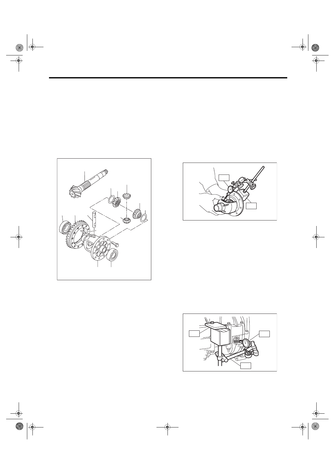
(A) Drive pinion shaft
(B) Hypoid driven gear

(C) Pinion shaft
(D) Straight pin

(E) Adjusting washer

(F) Differential bevel gear

(G) Differential bevel pinion

(H) Roller bearing

(I) Differential case

(I)

(H)

(D)

(C)

(B)

(E)

(F)

(G)

(F)

(E)

(A)

(H)

(G)

MT-01074

MT-00285

ST1

ST2

MT-00293

ST1

ST2

ST3

5MT-74

Front Differential Assembly

MANUAL TRANSMISSION AND DIFFERENTIAL

3. TOOTH CONTACT OF HYPOID GEAR

Check tooth contact of hypoid gear as follows: Ap-

ply a thin uniform coat of red lead on both teeth sur-

faces on 3 or 4 teeth of the hypoid gear. Move the

hypoid gear back and forth by turning the transmis-

sion main shaft until a definite contact pattern is de-

veloped  on  the  hypoid  gear,  and  judge  whether

face contact is correct. When the contact pattern is

not  correct,  adjust.  <Ref.  to  5MT-74,  ADJUST-

MENT, Front Differential Assembly.>

• Tooth contact is correct.

F: ADJUSTMENT

1. BEVEL PINION GEAR BACKLASH

1) Disassemble  the  front  differential  assembly.

<Ref. to 5MT-70, DISASSEMBLY, Front Differen-

tial Assembly.>

2) Select a suitable adjusting washer for the differ-

ential bevel gear from the table and install.

3) Adjust until the standard value is obtained.
Backlash:

Standard

0.13 — 0.18 mm (0.0051 — 0.0071 in)

2. HYPOID GEAR BACKLASH

Adjust the backlash by turning the side retainer in

the RH side case.

ST 18630AA010 WRENCH COMPL RETAIN-

ER

NOTE:

Each  time  the  side  retainer  rotates  by  one  notch

(A), the backlash changes by 0.05 mm (0.020 in).

(A) Toe
(B) Coast side

(C) Heel
(D) Drive side

Adjusting washer

Part No.

Thickness mm (in)

803038021

0.925 — 0.950

(0.0364 — 0.0374)

803038022

0.975 — 1.000

(0.0384 — 0.0394)

803038023

1.025 — 1.050

(0.0404 — 0.0413)

MT-01402

(B)

(D)

(C)

(A)

MT-00176

ST

MT-02603

(A)

5MT-75

Front Differential Assembly

MANUAL TRANSMISSION AND DIFFERENTIAL

3. TOOTH CONTACT OF HYPOID GEAR

1) Adjust until correct teeth contact is obtained.

2) Check  tooth  contact,  and  perform  the  adjust-

ment as follows.

• Correct tooth contact

Check  item:  Tooth  contact  surface  is  slightly

shifted toward the toe side under a no-load con-

dition. (When driving, it moves towards the heel

side.)

• Face contact

Check item: Backlash is too large.

Contact pattern

Corrective action: Tighten the side retainer to move

the driven gear closer to the drive pinion shaft.

• Flank contact

Check item: Backlash is too small.

Contact pattern

Corrective action: Loosen the side retainer to move

the driven gear away from the drive pinion shaft.

• Toe contact (inside contact)

Check item: Teeth contact area is too small.

Contact pattern

Corrective  action:  Increase  the  thickness  of  drive

pinion shim and tighten the side retainer to move

the driven gear closer to the drive pinion shaft ac-

cording to the procedure for bringing drive pinion

shaft away from driven gear.

(A) Toe side
(B) Heel side

(A)

(B)

MT-01401

AT-00208

MT-01799

AT-00209

MT-01800

AT-00210

AT-00213

5MT-76

Front Differential Assembly

MANUAL TRANSMISSION AND DIFFERENTIAL

• Heel contact (outside end contact)

Check item: Teeth contact area is too small.

Contact pattern

Corrective  action:  Reduce  the  thickness  of  drive

pinion shim and loosen the side retainer to move

the driven gear away from the drive pinion accord-

ing to the procedure for moving drive pinion shaft

closer to the driven gear.

AT-00211

AT-00212


Content   ..  411  412  413  414   ..