Subaru Impreza 3 / Impreza WRX / Impreza WRX STI. Manual - part 411
 

  Index      Subaru     Subaru Impreza 3 / Impreza WRX / Impreza WRX STI - service repair manual 2008-2014 year


Search            


Content   ..  409  410  411  412   ..


Subaru Impreza 3 / Impreza WRX / Impreza WRX STI. Manual - part 411


5MT-65

Drive Pinion Shaft Assembly

MANUAL TRANSMISSION AND DIFFERENTIAL

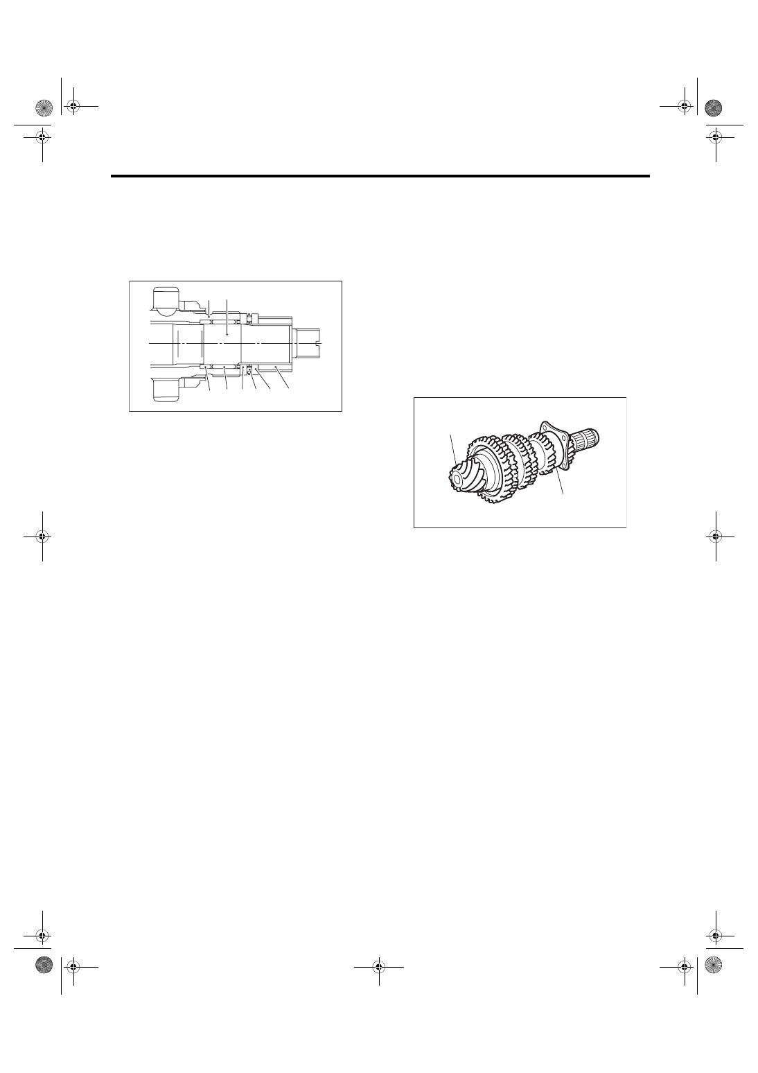
14) Install  the  drive  pinion  collar,  needle  bearing,

adjusting  washer  No.  2,  thrust  bearing,  adjusting

washer No. 1 and differential bevel gear sleeve in

this order.
NOTE:

Be careful to install the spacer in the proper direc-

tion.

15) Adjust  the  thrust  bearing  preload.  <Ref.  to

5MT-66,  THRUST  BEARING  PRELOAD,  AD-

JUSTMENT, Drive Pinion Shaft Assembly.>

E: INSPECTION

Disassembled parts should be washed with clean-

ing solvent first, then inspected carefully.

1) Bearing

Replace the bearings in the following cases.

• When  the  bearing  balls,  outer  races  and  inner

races are broken or rusty.

• When the bearing is worn.

• When the bearings fail to turn smoothly or emit

noise in rotation after gear oil lubrication.

• The ball bearing on the rear side of the drive pin-

ion shaft should be checked for smooth rotation be-

fore  the  drive  pinion  shaft  assembly  is

disassembled.  In this case, because a preload is

working  on  the  bearing,  its  rotation  feels  like  it  is

slightly dragging unlike other bearings.

• When bearing has other defects.

2) Bushing (each gear)

Replace the bushing in following cases.

• When the sliding surface is damaged or abnor-

mally worn.

• When the inner wall is abnormally worn.

3) Gear

Replace gears in the following cases.

• Replace the gear with new part if its tooth surfac-

es are broken, damaged or excessively worn.

• Correct or replace if the cone that contacts the

baulk ring is rough or damaged.

• Correct or replace if the inner surface or end face

is damaged.

4) Baulk ring, synchro cone

Replace the baulk ring and synchro cone in the fol-

lowing cases.

• When the inner surface and end face are dam-

aged.

• When the baulk ring inner surface is abnormally

or partially worn down.

• When the contact surface of the baulk ring insert

section is cracked or abnormally worn.

(A) Driven shaft
(B) Drive shaft

(C) Drive pinion collar
(D) Needle bearing (25 × 30 × 20)

(E) Adjusting washer No. 2 (25 × 36 × t)

(F) Thrust bearing (25 × 37.5 × 3)

(G) Adjusting washer No. 1 (25 × 36 × t)

(H) Differential bevel gear sleeve

MT-00263

(A) (B)

(C) (D) (E) (F) (G) (H)

(A) Drive pinion shaft
(B) Ball bearing

MT-00264

(A)

(B)

5MT-66

Drive Pinion Shaft Assembly

MANUAL TRANSMISSION AND DIFFERENTIAL

• If the gap between the end faces of the baulk ring

and  the  gear  splined  part  is  excessively  small,

check  the  clearance  (A)  while  pressing  the  ring

against the cone.
Clearance (A):

0.5 mm (0.020 in) or more

• Apply gear oil to the cone of the gear and while

press-fitting the baulk ring, check there is no rota-

tion in the circumferential direction.

5) Coupling sleeve and synchronizer hub

• Check  the  slipping  condition  of  the  coupling

sleeve.

• Check  the  splines  on  the  coupling  sleeve  and

synchronizer hub for wear.

6) Shifting insert key

Replace the shifting insert key if deformed, exces-

sively worn or defective in any way.

7) Ball detent

Replace  the  ball  detent  if  deformed,  excessively

worn or defective in any way.

8) Oil seal

Replace  the  oil  seal  if  the  lip  is  deformed,  hard-

ened, worn or defective in any way.

9) O-ring

Replace the O-ring if the sealing face is deformed,

hardened, damaged, worn or defective in any way.

F: ADJUSTMENT

1. THRUST BEARING PRELOAD

1) Select a suitable adjusting washer No. 1 so that

dimension (H) will be zero in a visual check. Posi-

tion the washer (18.3 × 30 × t) and lock washer (18

× 30 × 2) and attach the lock nut.

MT-01674

(A)

MT-00267

(H)

5MT-67

Drive Pinion Shaft Assembly

MANUAL TRANSMISSION AND DIFFERENTIAL

2) Using  the  ST1,  ST2  and  ST3,  tighten  the  new

lock nut to the specified torque.
NOTE:

• Use new lock nuts and lock washers.

• Make  sure  the  lock  washer  is  installed  in  the

proper direction.
Tightening torque:

120 N·m (12.2 kgf-m, 88.5 ft-lb)

ST1 899884100

HOLDER

ST2 498427100

STOPPER

ST3 899988608

SOCKET WRENCH (27)

3) After  removing  the  ST2,  measure  the  starting

torque using torque driver.

ST1 899884100

HOLDER

ST3 899988608

SOCKET WRENCH (27)

Starting torque:

0.3 — 0.8 N·m (0.03 — 0.08 kgf-m, 0.22 — 0.59 

ft-lb)

4) If the starting torque is not within the specified

limit,  select  new  adjusting  washer  No.  1  and  re-

check starting torque.

(A) Lock nut
(B) Lock washer

(C) Nut side

ST1

ST2

ST3

MT-02392

(C)

(A)

(B)

(A) Adjusting washer No. 1
(B) Adjusting washer No. 2

Adjusting washer No. 1

Part No.

Thickness mm (in)

803025051

3.925 (0.1545)

803025052

3.950 (0.1555)

803025053

3.975 (0.1565)

803025054

4.000 (0.1575)

803025055

4.025 (0.1585)

803025056

4.050 (0.1594)

803025057

4.075 (0.1604)

MT-00269

ST1

ST3

MT-00270

( A )

( B )

5MT-68

Drive Pinion Shaft Assembly

MANUAL TRANSMISSION AND DIFFERENTIAL

5) If  the  specified  starting  torque  cannot  be  ob-

tained by the selection of adjusting washer No. 1,

select adjusting washer No. 2 from the list below.

Repeat  steps  1)  through  4)  to  adjust  starting

torque.

6) Recheck  that  the  starting  torque  is  within  the

specified range, then crimp the lock nut at four po-

sitions.
CAUTION:

When crimping the lock nut, be careful not to

crack it.

(A) Adjusting washer No. 1
(B) Adjusting washer No. 2

Starting torque

Dimension H

Adjusting washer No. 2

Low

Small

Select thicker one.

High

Large

Select thinner one.

Adjusting washer No. 2

Part No.

Thickness mm (in)

803025059

3.850 (0.1516)

803025054

4.000 (0.1575)

803025058

4.150 (0.1634)

MT-00270

( A )

( B )


Content   ..  409  410  411  412   ..