Subaru Impreza 3 / Impreza WRX / Impreza WRX STI. Manual - part 412
 

  Index      Subaru     Subaru Impreza 3 / Impreza WRX / Impreza WRX STI - service repair manual 2008-2014 year


Search            


Content   ..  410  411  412  413   ..


Subaru Impreza 3 / Impreza WRX / Impreza WRX STI. Manual - part 412


5MT-69

Front Differential Assembly

MANUAL TRANSMISSION AND DIFFERENTIAL

17.Front Differential Assembly

A: REMOVAL

1) Remove  the  manual  transmission  assembly

from  the  vehicle.  <Ref.  to  5MT-23,  REMOVAL,

Manual Transmission Assembly.>

2) Remove the transfer case together with the ex-

tension case assembly. <Ref. to 5MT-35, REMOV-

AL,  Transfer  Case  and  Extension  Case

Assembly.>

3) Remove  the  transmission  case.  <Ref.  to  5MT-

49, REMOVAL, Transmission Case.>

4) Remove the drive pinion shaft assembly. <Ref.

to 5MT-58, REMOVAL, Drive Pinion Shaft Assem-

bly.>

5) Remove  the  main  shaft  assembly  for  single-

range.  <Ref.  to  5MT-53,  REMOVAL,  Main  Shaft

Assembly for Single-Range.>

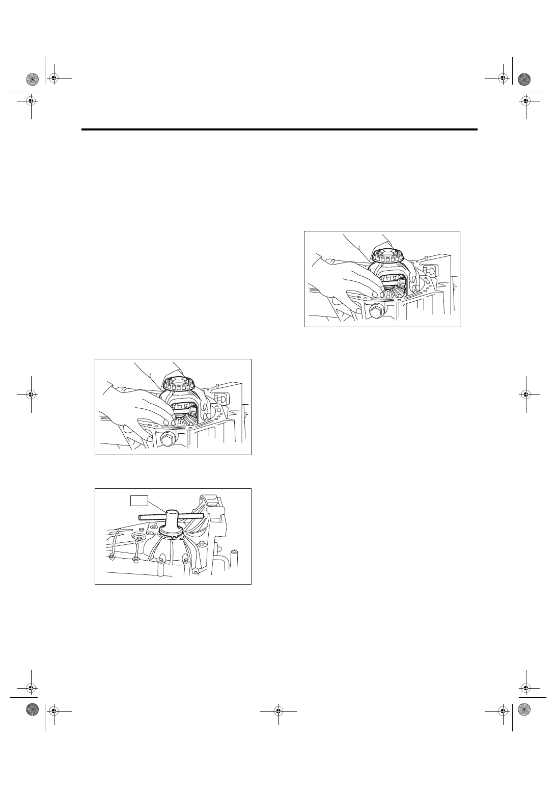
6) Remove the front differential assembly.
NOTE:

• Do  not  confuse  the  right  and  left  roller  bearing

outer races.

• Be careful not to damage the oil seal of retainer.

7) Remove the differential side retainers using ST.

ST 18630AA010 WRENCH COMPL RETAIN-

ER

8) Remove the bearing outer race from the trans-

mission case.

ST 398527700

PULLER ASSY

B: INSTALLATION

1) Install the differential side retainers using ST.

ST 18630AA010 WRENCH COMPL RETAIN-

ER

2) Install the bearing outer race to the transmission

case.

3) Install the front differential assembly.
NOTE:

Be careful not to bend the seal lips of oil seal.

4) Install the main shaft assembly for single-range.

<Ref. to 5MT-53, INSTALLATION, Main Shaft As-

sembly for Single-Range.>

5) Install the drive pinion shaft assembly. <Ref. to

5MT-58,  INSTALLATION,  Drive  Pinion  Shaft  As-

sembly.>

6) Install the transmission case. <Ref. to 5MT-50,

INSTALLATION, Transmission Case.>

7) Install the transfer case together with the exten-

sion case assembly. <Ref. to 5MT-35, INSTALLA-

TION,  Transfer  Case  and  Extension  Case

Assembly.>

8) Install the manual transmission assembly to the

vehicle. <Ref. to 5MT-26, INSTALLATION, Manual

Transmission Assembly.>

MT-00162

MT-00176

ST

MT-00162

5MT-70

Front Differential Assembly

MANUAL TRANSMISSION AND DIFFERENTIAL

C: DISASSEMBLY

1. DIFFERENTIAL CASE ASSEMBLY

1) Remove  the  twelve  bolts  and  remove  hypoid

driven gear.

2) Drive out the straight pin from differential assem-

bly toward hypoid driven gear side.

ST 899904100

STRAIGHT PIN REMOVER

3) Pull out the pinion shaft, and remove the differ-

ential  bevel  pinion,  differential  bevel  gear  and

washer.

4) Using the ST, remove the roller bearing.

ST 899524100

PULLER SET

(A) Hypoid driven gear

(A)

MT-00275

MT-00276

ST

(A) Pinion shaft
(B) Differential bevel pinion

(C) Differential bevel gear
(D) Washer

MT-00277

(A)

(D)

(D)

(C)

(C)

(B)

(B)

MT-00278

ST

5MT-71

Front Differential Assembly

MANUAL TRANSMISSION AND DIFFERENTIAL

2. SIDE RETAINER

1) Remove the O-ring.

2) Remove the oil seal.
NOTE:

Remove using the flat tip screwdriver.

D: ASSEMBLY

1. DIFFERENTIAL CASE ASSEMBLY

1) Install the differential bevel gear and differential

bevel  pinion  together  with  washer,  and  insert  the

pinion shaft.
NOTE:

Face the chamfered side of washer toward gear.

2) Measure the backlash between differential bevel

gear  and  differential  pinion.  If  backlash  is  out  of

specifications,  install  a  suitable  washer  to  adjust.

<Ref.  to  5MT-73,  BEVEL  PINION  GEAR  BACK-

LASH,  INSPECTION,  Front  Differential  Assem-

bly.>
NOTE:

Be  sure  the  pinion  gear  teeth  contacts  adjacent

gear teeth during measurement.

ST1 498247001

MAGNET BASE

ST2 498247100

DIAL GAUGE

Standard backlash

0.13 — 0.18 mm (0.0051 — 0.0071 in)

3) Align the pinion shaft and differential case with

each hole, and drive the straight pin into the holes

from the hypoid driven gear using the ST.
NOTE:

• Use a new straight pin.

• Lock the straight pin after installing.

ST 899904100

STRAIGHT PIN REMOVER

(A) Differential bevel pinion
(B) Differential bevel gear

(C) Pinion shaft

MT-02742

MT-02743

MT-00284

(A)

(B)

(C)

(A) Pinion shaft
(B) Differential case

(C) Straight pin

MT-00285

ST1

ST2

MT-00286

(A)

(C)

(B)

5MT-72

Front Differential Assembly

MANUAL TRANSMISSION AND DIFFERENTIAL

4) Install the roller bearing to differential case.
CAUTION:

Do not apply a load in excess of 10 kN (1 ton, 1.1

US ton, 1.0 Imp ton).
NOTE:

Be careful because the roller bearing outer races

are used as a set.

ST1 499277100

BUSHING 1-2 INSTALLER

ST2 398497701

ADAPTER

5) Install the hypoid driven gear to the differential

case using twelve bolts.
Tightening torque:

T: 62 N·m (6.3 kgf-m, 45.7 ft-lb)

2. SIDE RETAINER

1) Install the oil seal.
NOTE:

• Use a new oil seal.

• Apply  transmission  gear  oil  to  the  oil  seal  lips,

and install the oil seal while being careful not to de-

form the lip.

• Using the ST, install the oil seal by lightly tapping

with a plastic hammer.

ST 18675AA000 DIFFERENTIAL SIDE OIL 

SEAL INSTALLER

2) Install the O-ring.
NOTE:

• Use new O-rings.

• Apply gear oil to O-ring.

• Do not stretch or damage the O-ring.

(A) Hypoid driven gear
(B) Differential case

MT-00287

ST1

ST2

MT-01216

(B)

(A)

T

MT-00289

ST

MT-02742


Content   ..  410  411  412  413   ..