Subaru Impreza 3 / Impreza WRX / Impreza WRX STI. Manual - part 409


  Index      Subaru     Subaru Impreza 3 / Impreza WRX / Impreza WRX STI - service repair manual 2008-2014 year


Search            


Content   ..  407  408  409  410   ..


Subaru Impreza 3 / Impreza WRX / Impreza WRX STI. Manual - part 409


5MT-57

Main Shaft Assembly for Single-Range

MANUAL TRANSMISSION AND DIFFERENTIAL

• When the ring inner surface is abnormally or par-

tially worn down.

• When  the  contact  surface  of  the  synchronizer

ring insert section is cracked or abnormally worn.

• If the gap between the end faces of the ring and

the  gear  splined  part  is  excessively  small,  check

the  clearance  (A)  while  pressing  the  ring  against

the cone.
Clearance (A):

0.5 mm (0.020 in) or more

Single cone

Double cone

• Apply gear oil to the cone of the gear and while

press-fitting the baulk ring, check there is no rota-

tion in the circumferential direction.

5) Shifting insert key

Replace  the  insert  key  if  deformed,  excessively

worn or defective in any way.

6) Oil seal

Replace  the  oil  seal  if  the  lip  is  deformed,  hard-

ened, worn or defective in any way.

7) Coupling sleeve and synchronizer hub

• Check  the  slipping  condition  of  the  coupling

sleeve.

• Check  the  splines  on  the  coupling  sleeve  and

synchronizer hub for wear.

8) O-ring

Replace the O-ring if the sealing face is deformed,

hardened, damaged, worn or defective in any way.

9) Gearshift mechanism

Repair  or  replace  the  gearshift  mechanism  if  ex-

cessively worn, bent or defective in any way.
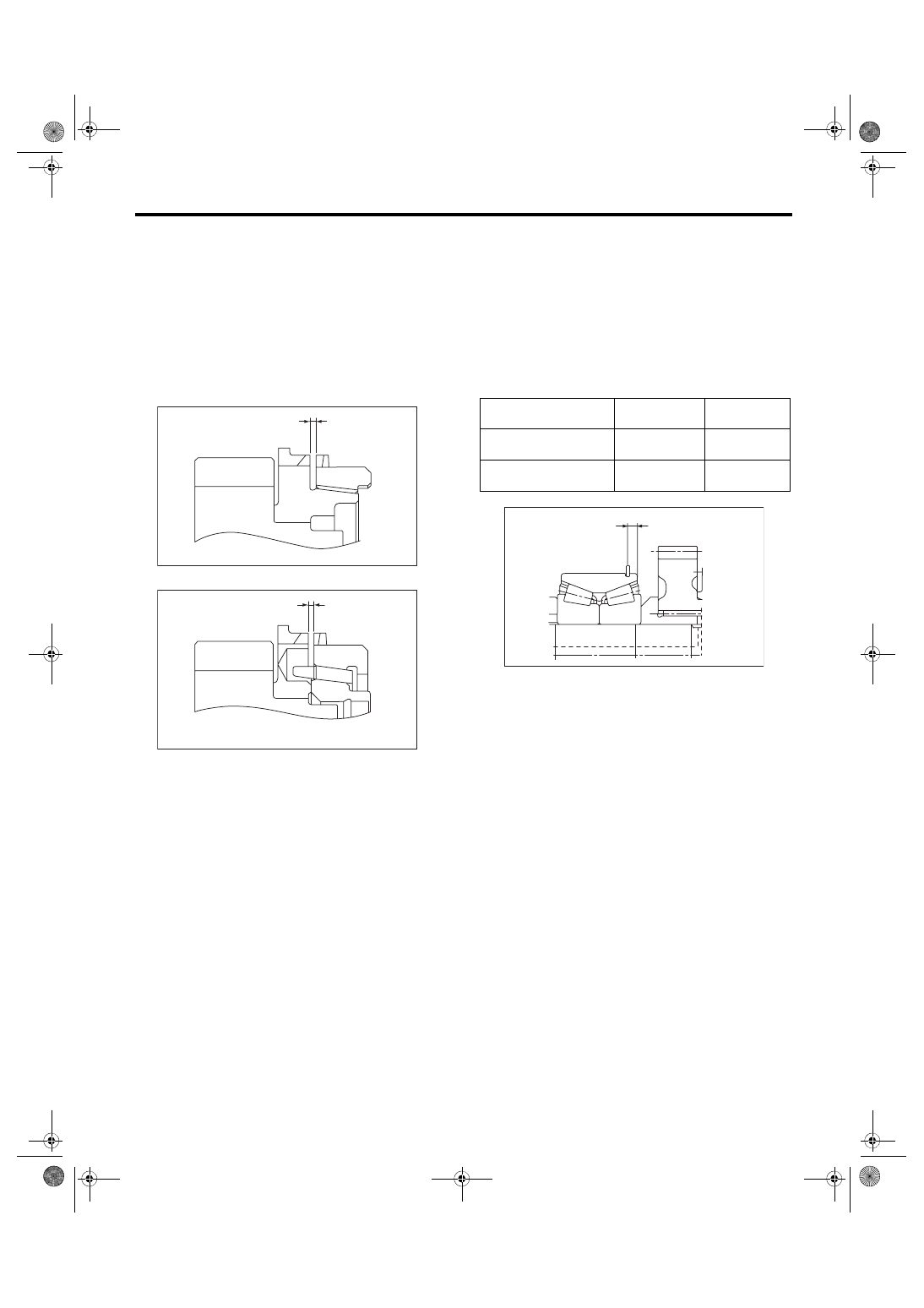
F: ADJUSTMENT

Selection of main shaft rear plate:

Measure the protrusion amount (A) of double taper

roller bearing from transmission main case surface,

and select a suitable plate in the following table.
NOTE:

Before measuring, tap the end of main shaft with a

plastic hammer lightly in order to make the clear-

ance  zero  between  the  main  case  surface  and

moving flange of bearing.

MT-01673

(A)

MT-01674

(A)

Dimension (A)

mm (in)

Part No.

Mark

4.00 — 4.13

(0.1575 — 0.1626)

32294AA041

1

3.87 — 4.00

(0.1524 — 0.1575)

32294AA051

2

MT-01807

(A)

5MT-58

Drive Pinion Shaft Assembly

MANUAL TRANSMISSION AND DIFFERENTIAL

16.Drive Pinion Shaft Assembly

A: REMOVAL

1) Remove  the  manual  transmission  assembly

from  the  vehicle.  <Ref.  to  5MT-23,  REMOVAL,

Manual Transmission Assembly.>

2) Remove the transfer case together with the ex-

tension case assembly. <Ref. to 5MT-35, REMOV-

AL,  Transfer  Case  and  Extension  Case

Assembly.>

3) Remove  the  transmission  case.  <Ref.  to  5MT-

49, REMOVAL, Transmission Case.>

4) Remove the drive pinion shaft assembly.
NOTE:

Use a hammer handle, etc. to remove if too tight.

B: INSTALLATION

1) Remove the front differential assembly.

2) Hypoid  gear  set  match  mark/No.:  The  number

(A) on top of the drive pinion, and the number on

the hypoid driven gear are set numbers for the two

gears. Use a pair having the same numbers.

The figure (B) below shows a number for shim ad-

justment. If no number is shown, the value is zero.

3) Place the drive pinion shaft assembly on trans-

mission main case RH without shim and tighten the

bearing mounting bolts.

4) Check and adjust the ST.

(1) Loosen the two bolts and adjust so that the

scale indicates 0.5 correctly when the plate end

and the scale end are on the same level.

(2) Tighten the two bolts.

ST 499917500

DRIVE PINION GAUGE 

ASSY

5) Position the ST by inserting the knock pin of ST

into the knock hole of transmission case.

ST 499917500

DRIVE PINION GAUGE 

ASSY

6) Slide the drive pinion gauge scale with finger tip

and read the value at the point where it matches

with the end face of drive pinion.

ST 499917500

DRIVE PINION GAUGE 

ASSY

7) The  thickness  of  shim  shall  be  determined  by

adding  the  value  indicated  on  drive  pinion  to  the

value indicated on the ST. (Add if the number on

drive  pinion  is  prefixed  by  +,  and  subtract  if  the

number is prefixed by –.)

ST 499917500

DRIVE PINION GAUGE 

ASSY

(A) Main shaft ASSY for single-range
(B) Drive pinion shaft ASSY

(A) Set number
(B) Number for shim adjustment

MT-00161

( A )

( B )

MT-00990

(A)

(B)

(A)

+0.1

(A) Plate
(B) Scale

(A) Adjust the clearance to zero without shim.

MT-00242

(A)

(B)

ST

MT-00243

(A)

ST

5MT-59

Drive Pinion Shaft Assembly

MANUAL TRANSMISSION AND DIFFERENTIAL

8) Select one to three shims in the following table

for the value determined as described above, and

take the shim(s) which thickness is closest to the

said value.

9) Install  the  front  differential  assembly.  <Ref.  to

5MT-69,  INSTALLATION,  Front  Differential  As-

sembly.>

10) Fit  the  transmission  case  knock  pin  to  the

knock pin hole of the roller bearing and install the

drive pinion shaft assembly.

11) Install  the  main  shaft  assembly  for  single-

range.  <Ref.  to  5MT-53,  INSTALLATION,  Main

Shaft Assembly for Single-Range.>

12) Check each shifter fork. <Ref. to 5MT-81, IN-

SPECTION, Shifter Fork and Rod.>

13) Install the transmission case. <Ref. to 5MT-50,

INSTALLATION, Transmission Case.>

14) Install the transfer case together with the exten-

sion case assembly. <Ref. to 5MT-35, INSTALLA-

TION,  Transfer  Case  and  Extension  Case

Assembly.>

15) Install the manual transmission assembly to the

vehicle. <Ref. to 5MT-26, INSTALLATION, Manual

Transmission Assembly.>

C: DISASSEMBLY

NOTE:

Attach a cloth to the end of driven shaft (on the fric-

tional side of the thrust needle bearing) to prevent

damage during disassembly or reassembly.

1) Flatten the tab of the lock nut. Remove the lock

nut with ST1, ST2 and ST3.

ST1 899884100

HOLDER

ST2 498427100

STOPPER

ST3 899988608

SOCKET WRENCH (27)

2) Draw out the drive pinion shaft from driven shaft.

Remove the differential bevel gear sleeve, adjust-

ing  washer  No.  1,  adjusting  washer  No.  2,  thrust

bearing, needle bearing and drive pinion collar.

Drive pinion shim

Part No.

Thickness mm (in)

32295AA031

0.150 (0.0059)

32295AA041

0.175 (0.0069)

32295AA051

0.200 (0.0079)

32295AA061

0.225 (0.0089)

32295AA071

0.250 (0.0098)

32295AA081

0.275 (0.0108)

32295AA091

0.300 (0.0118)

32295AA101

0.500 (0.0197)

(A) Differential bevel gear sleeve
(B) Adjusting washer No. 1 (25 × 37.5 × t)

(C) Thrust bearing (25 × 37.5 × 3)
(D) Adjusting washer No. 2 (25 × 37.5 × t)

(E) Needle bearing (25 × 30 × 20)

(F) Drive pinion collar

(G) Needle bearing (30 × 37 × 23)

(H) Thrust bearing (33 × 50 × 3)

MT-00244

ST1

ST2

ST3

MT-00245

( B )

( D )

( C )

( A )

( F )

( H )

( G )

( E )

5MT-60

Drive Pinion Shaft Assembly

MANUAL TRANSMISSION AND DIFFERENTIAL

3) Remove the roller bearing and washer using ST

and a press.

ST 498077000

REMOVER

4) Flatten the tab of the lock nut. Remove the lock

nut using ST1 and ST2.

ST1 499987300

SOCKET WRENCH (50)

ST2 899884100

HOLDER

5) Remove the 5th driven gear using ST.

ST 499857000

5TH DRIVEN GEAR REMOV-

ER

6) Remove the woodruff key.

7) Remove the double taper roller bearing and 3rd-

4th driven gear using ST1 and ST2.

ST1 499757002

INSTALLER

ST2 899714110

REMOVER

8) Remove the key.

9) Remove  the  2nd  driven  gear,  inner  baulk  ring,

synchro cone and outer baulk ring.

10) Remove the 1st driven gear, inner baulk ring,

synchro cone, outer baulk ring, 2nd gear bushing

and gear & hub assembly using ST1 and ST2.

MT-00246

ST

MT-00247

ST1

ST2

MT-00248

S T

(A) 2nd driven gear
(B) Synchro cone

(C) Inner baulk ring
(D) Outer baulk ring

(A) 1st driven gear
(B) Synchro cone

(C) Inner baulk ring
(D) Outer baulk ring

(E) Gear & hub ASSY

(F) 2nd gear bushing

MT-00249

ST1

ST2

(A)

(B)

(C)

(D)

MT-02396

MT-02397

(D)

(E)

(F)

(C)

(B)

(A)


Content   ..  407  408  409  410   ..