Subaru Impreza 3 / Impreza WRX / Impreza WRX STI. Manual - part 392
CS-19
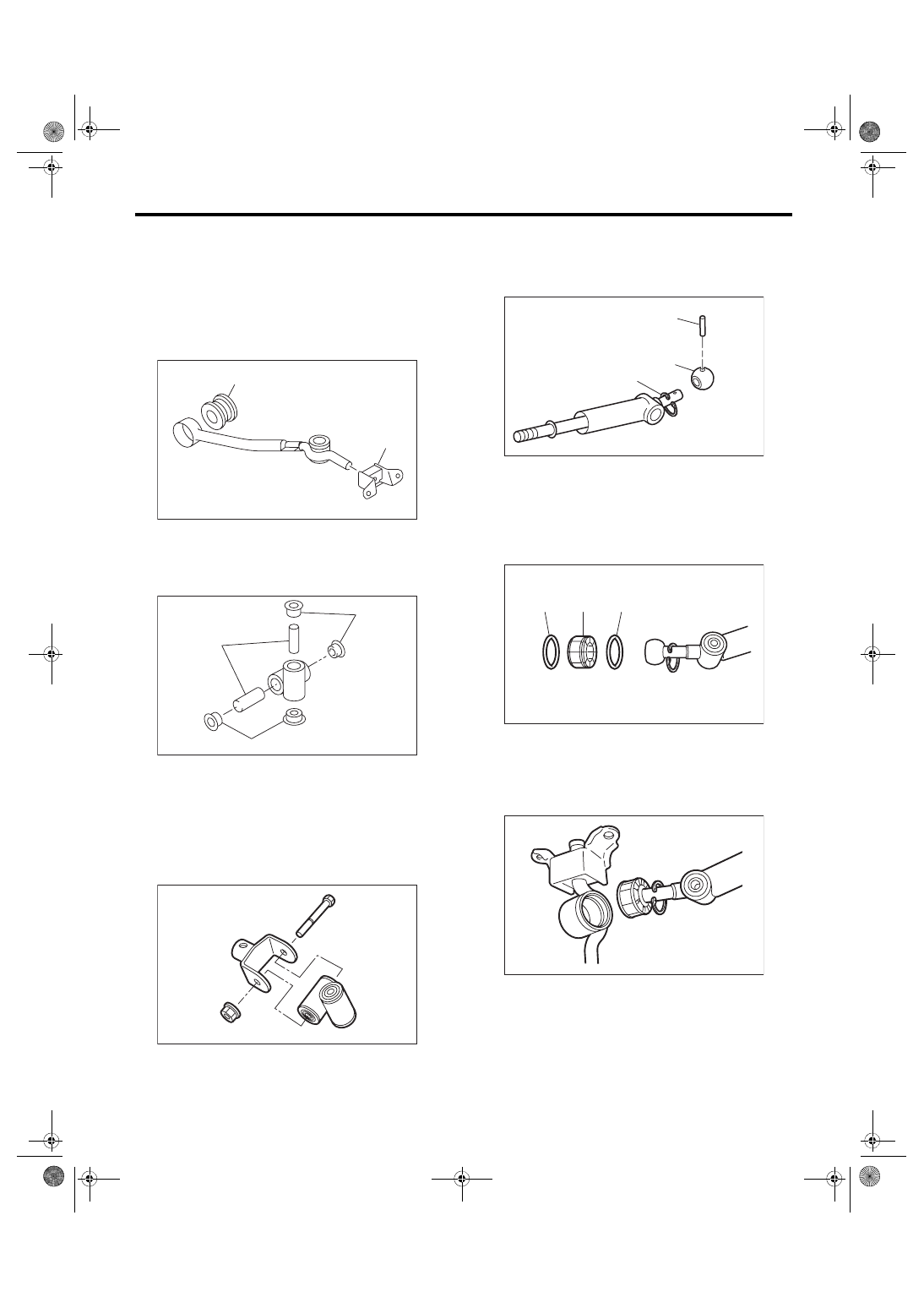
MT Gear Shift Lever
CONTROL SYSTEMS
2. EXCEPT FOR STI MODEL
NOTE:
• Clean all the parts before assembly.
• Apply NIGTIGHT LYW No. 2 grease or equiva-
lent to each part. <Ref. to CS-4, 5MT GEAR SHIFT
LEVER, COMPONENT, General Description.>
1) Mount the bushing and cushion rubber to the
stay.
2) Install the bushing and spacer to boss.
3) Using new self-locking nuts, install the boss to
the joint.
Tightening torque:
12 N·m (1.2 kgf-m, 8.9 ft-lb)
4) Install the snap ring to gear shift lever and install
the bushing.
NOTE:
Apply grease to the bushing.
5) Apply grease to the bushing and O-ring, and
then install to gear shift lever.
6) Apply sufficient grease into boss, and then install
the gear shift lever to the stay.
(A) Bushing
(B) Cushion rubber
(A) Bushing
(B) Spacer
CS-00061
(A)
(B)
CS-00238
(B)
(A)
(A)
CS-00322
(A) Spring pin
(B) Bushing
(C) Snap ring
(A) O-ring
(B) Bushing
CS-01414
(B)
(A)
(C)
CS-01415
(B)
(A)
(A)
CS-01413