Subaru Impreza 3 / Impreza WRX / Impreza WRX STI. Manual - part 390


  Index      Subaru     Subaru Impreza 3 / Impreza WRX / Impreza WRX STI - service repair manual 2008-2014 year


Search            


Content   ..  388  389  390  391   ..


Subaru Impreza 3 / Impreza WRX / Impreza WRX STI. Manual - part 390


CS-11

MT Gear Shift Lever

CONTROL SYSTEMS

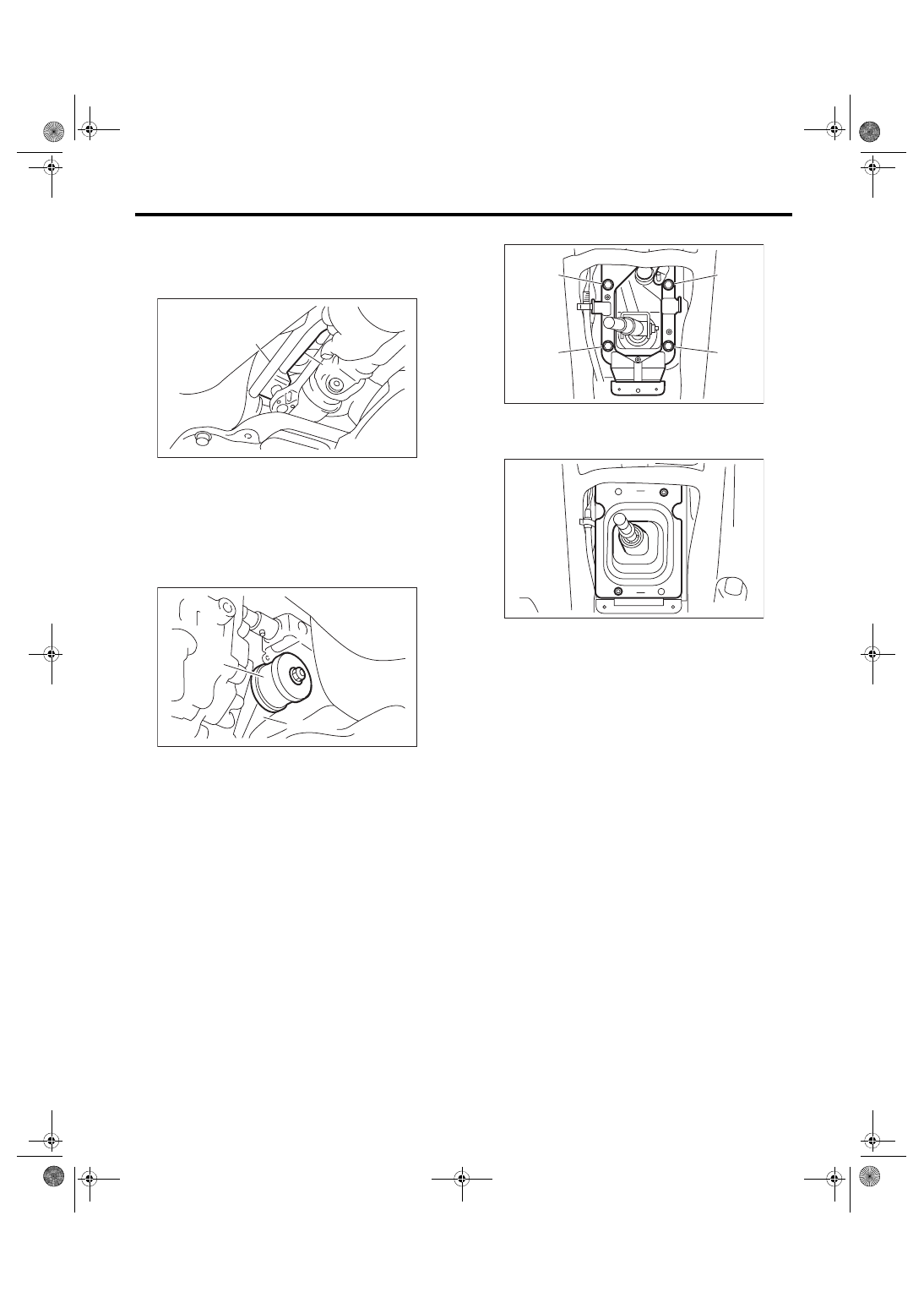
5) Using new self-locking nuts, connect the rod to

the joint.
Tightening torque:

12 N·m (1.2 kgf-m, 8.9 ft-lb)

6) Using new self-locking nuts, connect the stay to

the transmission bracket.
Tightening torque:

18 N·m (1.8 kgf-m, 13.3 ft-lb)

7) Install the heat shield cover. <Ref. to EI-74, IN-

STALLATION, Heat Shield Cover.>

8) Install  the  center  exhaust  pipe  (rear).  <Ref.  to

EX(w/o STI)-2, General Description.>

9) Install the plate COMPL to the body.
Tightening torque:

18 N·m (1.8 kgf-m, 13.3 ft-lb)

(1) Set the plate COMPL to the vehicle.

(2) Temporarily tighten the bolt (A).

(3) Tighten the bolt (B).

(4) Tighten the bolt (A).

(5) Tighten the bolts (C) and (D).

10) Install the harness clamp to the plate.

11) Install the boot and insulator assembly, and se-

cure with a clamp.

12) Install the console side cover and console front

panel.  <Ref.  to  EI-54,  INSTALLATION,  Center

Console.>

13) Install the console box. <Ref. to EI-51, INSTAL-

LATION, Console Box.>

14) Install the gear shift knob.

15) Make sure the gears can be shifted accurately

into each gear.

16) Connect the battery ground terminal.

(A) Stay
(B) Rod

(A) Stay
(B) Transmission bracket

CS-00051

(A)

(B)

MT-02037

(A)

(B)

CS-00737

(B)

(A)

(C)

(D)

CS-00732

CS-12

MT Gear Shift Lever

CONTROL SYSTEMS

C: DISASSEMBLY

1. STI MODEL

1) Remove the spring pin from the slider.

2) Remove the slider and spring.

3) Cut off the band clip.

4) Remove the reverse check cable from the cable

plate.

5) Remove the reverse check cable from the gear

shift assembly.

6) Remove the holder and spring.

(A) Slider
(B) Spring pin

(A) Slider
(B) Spring

CS-00225

(A)

(B)

CS-00226

(A)

(B)

CS-00227

(A) Cable plate
(B) Reverse check cable

(A) Holder

CS-00228

(A)

(B)

CS-00229

(A)

CS-00230

CS-13

MT Gear Shift Lever

CONTROL SYSTEMS

7) Disassemble the lock wire.
NOTE:

Do not reuse the lock wire.

8) Remove the boss from the rod.

9) Remove the rod from lever.

10) Separate the rod and inner boot.

11) Remove the snap ring from the stay.

12) Separate the gear shift lever and the stay.

13) Remove the O-ring and bushing from the gear

shift lever.

(A) Lock wire

(A) Rod
(B) Boss

(A) Rod
(B) Lever

(C) Stay

CS-00231

(A)

CS-00232

(B)

(A)

CS-00233

(C)

(A)

(B)

(A) Snap ring

(A) O-ring
(B) Bushing

CS-00234

(A)

CS-00235

CS-00236

(A)

(B)

(A)

CS-14

MT Gear Shift Lever

CONTROL SYSTEMS

14) Remove  the  spring  pin,  and  then  remove  the

bushing and snap ring.

15) Remove the bushing and spacer from the boss.

16) Remove the bushing and cushion rubber from

the stay.

2. EXCEPT FOR STI MODEL

1) Remove the lock wires.

2) Remove the rod from lever.

3) Separate the rod and inner boot.

4) Remove the snap ring from the stay.

(A) Bushing
(B) Snap ring

(A) Bushing
(B) Spacer

(A) Bushing
(B) Stay

(C) Cushion rubber

CS-00237

(A)

(B)

CS-00238

(B)

(A)

(A)

CS-00239

(B)

(C)

(A)

(A) Lock wire

(A) Rod
(B) Lever

(C) Stay

(A) Snap ring

CS-00316

(A)

CS-00317

(A)

(B)

(C)

CS-00318

(A)


Content   ..  388  389  390  391   ..