Subaru Impreza 3 / Impreza WRX / Impreza WRX STI. Manual - part 391
CS-15
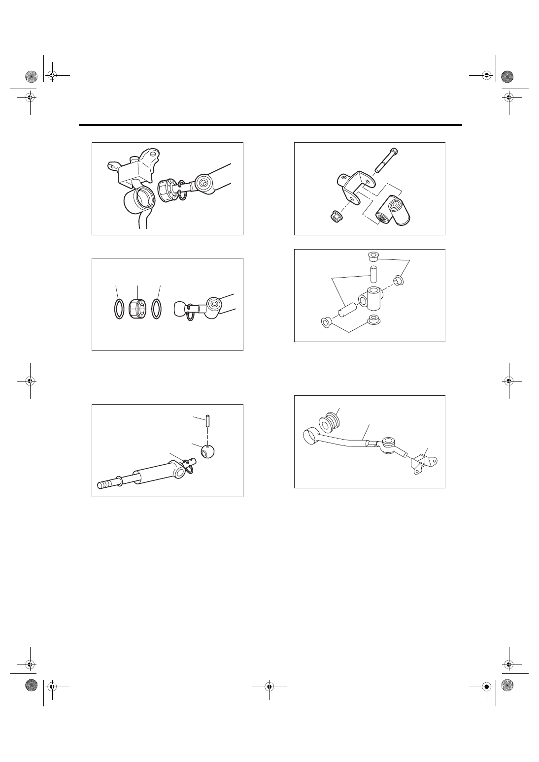
MT Gear Shift Lever
CONTROL SYSTEMS
5) Separate the gear shift lever and the stay.
6) Remove the O-ring and bushing from the gear
shift lever.
7) Remove the spring pin, and then remove the
bushing and snap ring.
8) Remove the boss from the joint.
9) Remove the bushing and spacer from the boss.
10) Remove the bushing and cushion rubber from
the stay.
(A) O-ring
(B) Bushing
(A) Spring pin
(B) Bushing
(C) Snap ring
CS-01413
CS-01415
(B)
(A)
(A)
CS-01414
(B)
(A)
(C)
(A) Bushing
(B) Spacer
(A) Bushing
(B) Stay
(C) Cushion rubber
CS-00322
CS-00238
(B)
(A)
(A)
CS-00058
(A)
(B)
(C)