Subaru Impreza 3 / Impreza WRX / Impreza WRX STI. Manual - part 78
ME(STI)-74
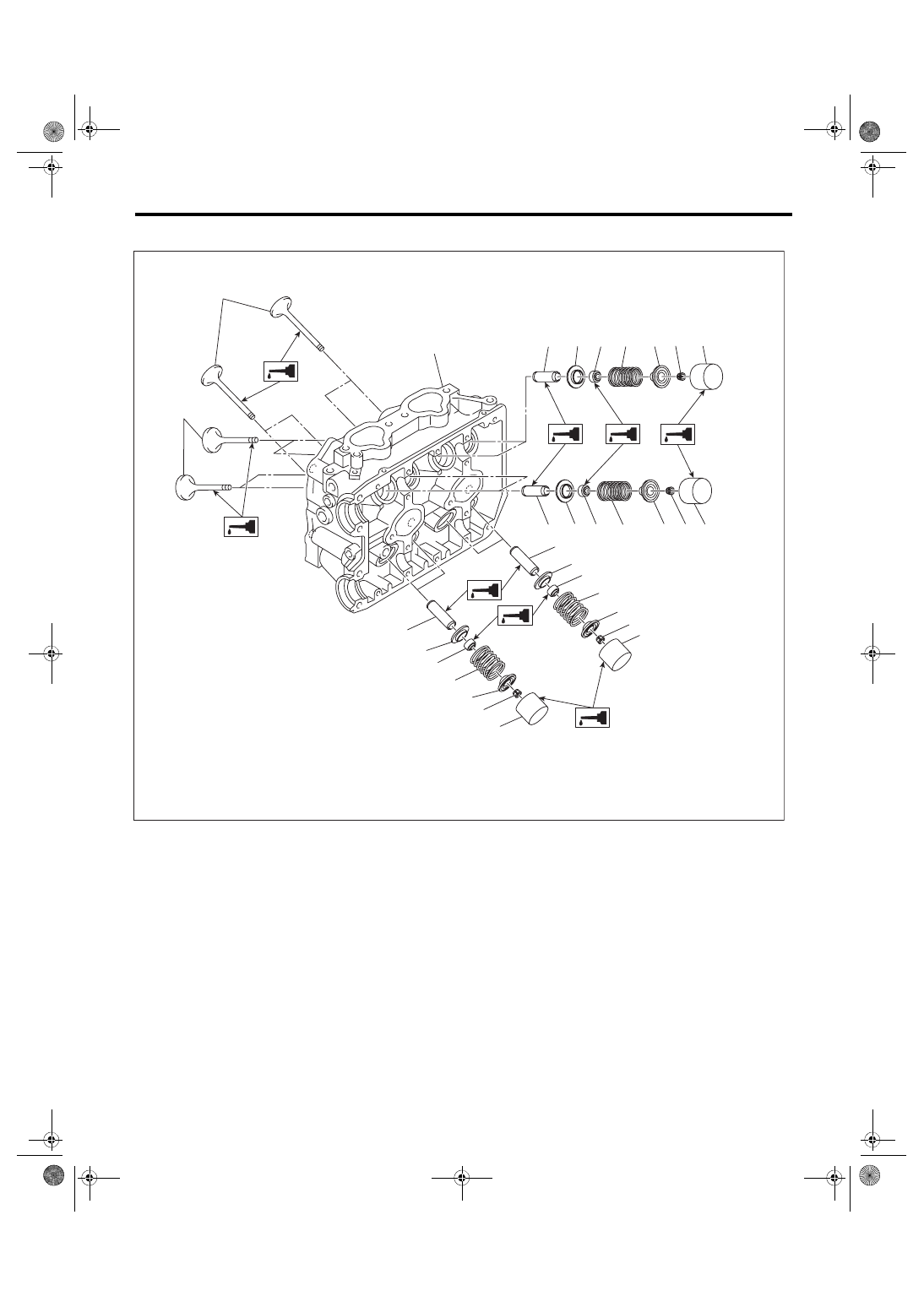
Cylinder Head
MECHANICAL
D: ASSEMBLY
(1)
Exhaust valve
(5)
Intake valve oil seal
(9)
Valve lifter
(2)
Intake valve
(6)
Valve spring
(10) Exhaust valve oil seal
(3)
Cylinder head
(7)
Valve spring retainer
(11) Intake valve guide
(4)
Valve spring seat
(8)
Valve spring retainer key
(12) Exhaust valve guide
(3)
(1)
(12)
(10)
(4)
(6)
(7)
(8)
(9)
(10)
(4)
(6)
(7)
(8)
(9)
ME-04990
(12)
(2)
(11)
(4) (5)
(6)
(7) (8)
(9)
(11)
(4) (5)
(6)
(7) (8) (9)