Subaru Impreza 3 / Impreza WRX / Impreza WRX STI. Manual - part 79


  Index      Subaru     Subaru Impreza 3 / Impreza WRX / Impreza WRX STI - service repair manual 2008-2014 year


Search            


Content   ..  77  78  79  80   ..


Subaru Impreza 3 / Impreza WRX / Impreza WRX STI. Manual - part 79


ME(STI)-78

Cylinder Head

MECHANICAL

5. VALVE SPRING

1) Check the valve springs for damage, free length,

and  tension.  Replace  the  valve  spring  if  it  is  not

within the standard value presented in the table.

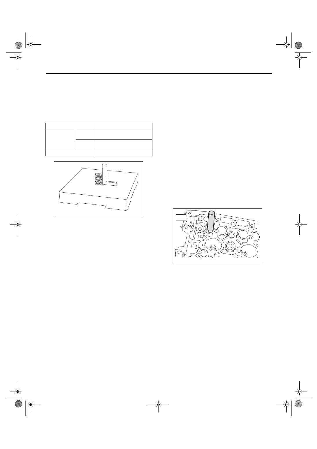
2) To measure the squareness of the valve spring,

stand the valve spring on a surface plate and mea-

sure its deflection at the top of the valve spring us-

ing a try square.

6. INTAKE AND EXHAUST VALVE OIL 

SEAL

1) For the following, replace the oil seal with a new

part. See the procedure 2) and subsequent for re-

placement procedures.

• When the lip is damaged.

• When the spring is out of the specified position.

• When  readjusting  the  surfaces  of  valve  and

valve seat.

• When replacing the valve guide.

2) Place the cylinder head on ST1, and use ST2 to

press-fit the oil seal.

ST1 498267600

CYLINDER HEAD TABLE

ST2 498857100

VALVE OIL SEAL GUIDE

NOTE:

• Apply engine oil to oil seal before press-fitting.

• When press-fitting the oil seal, do not use a ham-

mer to strike in.

• The intake valve oil seals and exhaust valve oil

seals are distinguished by their colors.
Color of rubber part:

Intake [Gray]

Exhaust [Green]

Free length

mm (in) 53.48 (2.106)

Tension/spring 
height
N (kgf, lbf)/mm 
(in)

Set

204.6 — 235.4 (20.86 — 24.00, 
46.00 — 52.93)/36.0 (1.417)

Lift

363.5 — 401.7 (37.07 — 40.96, 
81.73 — 90.32)/26.7 (1.051)

Squareness

2.5°, 2.3 mm (0.091 in) or less

ME-00283

ME-00133

ST2

ME(STI)-79

Cylinder Head

MECHANICAL

7. VALVE LIFTER

1) Check the valve lifter visually.

2) Measure the outer diameter of valve lifter.
Outer diameter of valve lifter:

Standard

34.959 — 34.975 mm (1.3763 — 1.3770 in)

3) Measure the inner diameter of valve lifter mating

surface on cylinder head.
Valve lifter mating surface inner diameter:

Standard

34.994 — 35.016 mm (1.3777 — 1.3786 in)

4) Check  the  clearance  between  valve  lifter  and

valve lifter mating surface. The clearance can be

checked by measuring the outer diameter of valve

lifter and the inner diameter of valve lifter. If it ex-

ceeds the standard or offset wear occurs, replace

the cylinder head.
Valve lifter and valve lifter mating surface clear-

ance:

Standard

0.019 — 0.057 mm (0.0007 — 0.0022 in)

ME-00134

ME-00135

ME(STI)-80

Cylinder Block

MECHANICAL

20.Cylinder Block

A: REMOVAL

NOTE:

Before conducting this procedure, drain the engine

oil completely.

1) Remove  the  engine  from  the  vehicle.  <Ref.  to

ME(STI)-30, REMOVAL, Engine Assembly.>

2) Remove the rear side belt. <Ref. to ME(STI)-40,

REAR SIDE BELT, REMOVAL, V-belt.>

3) Remove the intake manifold. <Ref. to FU(STI)-

17, REMOVAL, Intake Manifold.>

4) Remove the crank pulley. <Ref. to ME(STI)-47,

REMOVAL, Crank Pulley.>

5) Remove the timing belt cover. <Ref. to ME(STI)-

49, REMOVAL, Timing Belt Cover.>

6) Remove  the  timing  belt.  <Ref.  to  ME(STI)-50,

REMOVAL, Timing Belt.>

7) Remove the cam sprocket. <Ref. to ME(STI)-59,

REMOVAL, Cam Sprocket.>

8) Remove the crank sprocket. <Ref. to ME(STI)-

60, REMOVAL, Crank Sprocket.>

9) Remove the generator and A/C compressor with

their brackets.

10) Remove  the  camshaft.  <Ref.  to  ME(STI)-61,

REMOVAL, Camshaft.>

11) Remove the cylinder head. <Ref. to ME(STI)-

70, REMOVAL, Cylinder Head.>

12) Remove the clutch disc and cover. <Ref. to CL-

11, REMOVAL, Clutch Disc and Cover.>

13) Remove the flywheel. <Ref. to CL-14, REMOV-

AL, Flywheel.>

14) Remove the oil separator cover.

15) Remove the water by-pass pipe for heater.

16) Remove the oil filter. <Ref. to LU(STI)-31, RE-

MOVAL, Engine Oil Filter.>

17) Remove  the  oil  cooler.  <Ref.  to  LU(STI)-24,

REMOVAL, Engine Oil Cooler.>

18) Remove the water pump. <Ref. to CO(STI)-15,

REMOVAL, Water Pump.>

19) Remove the bolts which secure oil pump to cyl-

inder block.
NOTE:

When  disassembling  and  checking  the  oil  pump,

loosen the relief valve plug before removing the oil

pump.

20) Remove the oil pump from cylinder block using

a flat tip screwdriver.
CAUTION:

Be careful not to scratch the mating surface of

the cylinder block and oil pump.

21) Remove the front oil seal from the oil pump.

22) Remove the oil pan.

(1) Set the part so that the cylinder block LH is

on the upper side.

(2) Remove  the  bolts  which  secure  oil  pan  to

cylinder block.

(3) Insert an oil pan cutter blade between cylin-

der block-to-oil pan clearance and remove the

oil pan.

CAUTION:

Do  not  use  a  screwdriver  or  similar  tools  in

place of oil pan cutter.

23) Remove the oil strainer.

24) Remove the baffle plate.

LU-00015

ME-00138

ME(STI)-81

Cylinder Block

MECHANICAL

25) Remove the water tank pipe assembly from the

cylinder block RH.
NOTE:

Pinch the clamp of the water tank pipe assembly by

fitting the cut out in the ST with the protrusion on

the clamp as shown in the figure, and unlock the

clamp.

ST 18353AA000 CLAMP PLIERS

ME-04374

ST

(1)

Service hole plug

(4)

Piston pin

(7)

Seal washer

(2)

Gasket

(5)

Service hole cover

(8)

Washer

(3)

Snap ring

(6)

O-ring


ME-04723

(3)

(4)

(2)

(1)

(3)

(4)

(5)

(6)

(2)

(3)

(2)

(1)

(3)

(4)

(4)

(8)

(7)

(1)

(7)


Content   ..  77  78  79  80   ..