Subaru Impreza 3 / Impreza WRX / Impreza WRX STI. Manual - part 77


  Index      Subaru     Subaru Impreza 3 / Impreza WRX / Impreza WRX STI - service repair manual 2008-2014 year


Search            


Content   ..  75  76  77  78   ..


Subaru Impreza 3 / Impreza WRX / Impreza WRX STI. Manual - part 77


ME(STI)-70

Cylinder Head

MECHANICAL

19.Cylinder Head

A: REMOVAL

1) Remove  the  engine  from  the  vehicle.  <Ref.  to

ME(STI)-30, REMOVAL, Engine Assembly.>

2) Remove the rear side belt. <Ref. to ME(STI)-40,

REAR SIDE BELT, REMOVAL, V-belt.>

3) Remove the intake manifold. <Ref. to FU(STI)-

17, REMOVAL, Intake Manifold.>

4) Remove the crank pulley. <Ref. to ME(STI)-47,

REMOVAL, Crank Pulley.>

5) Remove the timing belt cover. <Ref. to ME(STI)-

49, REMOVAL, Timing Belt Cover.>

6) Remove  the  timing  belt.  <Ref.  to  ME(STI)-50,

REMOVAL, Timing Belt.>

7) Remove the cam sprocket. <Ref. to ME(STI)-59,

REMOVAL, Cam Sprocket.>

8) Remove  the  secondary  air  combination  valve.

<Ref.  to  EC(STI)-29,  REMOVAL,  Secondary  Air

Combination Valve.>

9) Remove the bolts which secure A/C compressor

bracket to cylinder head.

10) Remove the oil pipe. <Ref. to LU(STI)-25, RE-

MOVAL, Oil Pipe.>

11) Remove  the  camshaft.  <Ref.  to  ME(STI)-61,

REMOVAL, Camshaft.>

12) Remove  the  oil  level  gauge  guide.  (LH  side

only)

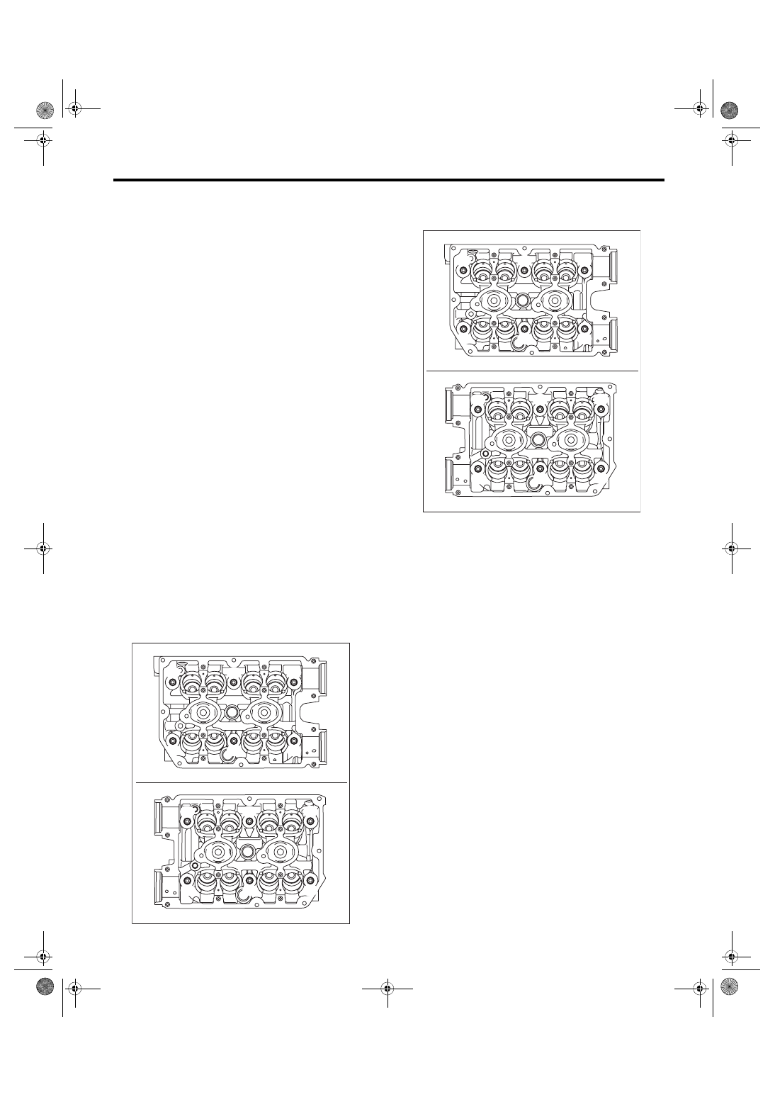
13) Remove the cylinder head bolts in alphabetical

order shown in the figure.
NOTE:

Leave  the  bolts  (A)  and  (D)  engaged  by  three  or

four threads to prevent the cylinder head from fall-

ing.

14) While tapping the cylinder head with a plastic

hammer, separate it from cylinder block. Remove

the bolts (A) and (D) to remove cylinder head.

15) Remove the cylinder head gasket.
CAUTION:

Be careful not to scratch the mating surface of

cylinder head and cylinder block.

B: INSTALLATION

1) Install the cylinder head to the cylinder block.
CAUTION:

Be careful not to scratch the mating surface of

cylinder head and cylinder block.
NOTE:

Use a new cylinder head gasket.

(1) Clean the bolt threads and the bolt holes in

the cylinder block

CAUTION:

To  avoid  erroneous  tightening  of  the  bolts,

clean out the bolt holes sufficiently by blowing

with compressed air to eliminate engine cool-

ant etc.

(2) Apply  a  sufficient  coat  of  engine  oil  to  the

washer and bolt thread.

(3) Tighten all bolts to 40 N·m (4.1 kgf-m, 29.5

ft-lb) in alphabetical order.

ME-05983

(F)

(D)

(C)

(E)

(B)

(D)

(F)

(A)

(B)

(E)

(C)

(A)

ME-05983

(F)

(D)

(C)

(E)

(B)

(D)

(F)

(A)

(B)

(E)

(C)

(A)

ME(STI)-71

Cylinder Head

MECHANICAL

(4) Retighten  all  bolts  to  95  N·m  (9.7  kgf-m,

70.1 ft-lb) in alphabetical order.

CAUTION:

If the bolt makes stick-slip sound during tight-

ening,  repeat  the  procedure  from  step  (1).  In

this case, the cylinder head gasket can be re-

used.

(5) Loosen all the bolts by 180° in the reverse

order of installing, and loosen them further by

180°.

(6) Tighten all bolts to 10 N·m (1.0 kgf-m, 7.4 ft-lb)

in alphabetical order.

(7) Retighten  all  bolts  to  30  N·m  (3.1  kgf-m,

22.1 ft-lb) in alphabetical order.

(8) Retighten  all  bolts  to  70  N·m  (7.1  kgf-m,

51.6 ft-lb) in alphabetical order.

(9) Retighten all bolts by 80 — 90° in alphabet-

ical order.

(10) Retighten all bolts by 40 — 45° in alphabet-

ical order.

CAUTION:

The tightening angle of the bolt should not ex-

ceed 45°.

(11) Retighten bolts (A) and (B) by 40 — 45°.

CAUTION:

Make sure the total “tightening angle” of steps

(10) and (11) does not exceed 90°.

2) Install the oil level gauge guide. (LH side only)
Tightening torque:

6.4 N·m (0.7 kgf-m, 4.7 ft-lb)

3) Install  the  camshaft.  <Ref.  to  ME(STI)-64,  IN-

STALLATION, Camshaft.>

4) Install the oil pipe. <Ref. to LU(STI)-27, INSTAL-

LATION, Oil Pipe.>

5) Install  the  A/C  compressor  bracket  on  cylinder

head.
Tightening torque:

36 N·m (3.7 kgf-m, 26.6 ft-lb)

6) Install  the  secondary  air  combination  valve.

<Ref. to EC(STI)-30, INSTALLATION, Secondary

Air Combination Valve.>

7) Install  the  cam  sprocket.  <Ref.  to  ME(STI)-59,

INSTALLATION, Cam Sprocket.>

8) Install the timing belt. <Ref. to ME(STI)-52, IN-

STALLATION, Timing Belt.>

9) Adjust the valve clearance. <Ref. to ME(STI)-29,

ADJUSTMENT, Valve Clearance.>

10) Install the rocker cover.

(1) Install the rocker cover gasket to the rocker

cover. (outer section and ignition coil section)

NOTE:

Use a new rocker cover gasket.

(2) Apply liquid gasket to the specified point of

the cylinder head.

NOTE:

Install within 5 min. after applying liquid gasket.
Liquid gasket:

THREE BOND 1217G (Part No. K0877Y0100) 

or equivalent

(3) Install the rocker cover onto cylinder heads.

Ensure the gasket is properly positioned during

installation.

ME-05984

(F)

(A)

(C)

(D)

(B)

(E)

(C)

(A)

(F)

(E)

(B)

(D)

ME-05981

ME(STI)-72

Cylinder Head

MECHANICAL

(4) Temporarily tighten the rocker cover bolts in

alphabetical order shown in the figure, and then

tighten to specified torque in alphabetical order.

Tightening torque:

6.4 N·m (0.7 kgf-m, 4.7 ft-lb)

11) Connect the PCV hose (A) and vacuum hose

(B) to the rocker cover.
NOTE:

Use a new clamp for the PCV hose (A), fit the cut

out in the ST with the protrusion on the clamp as

shown in the figure, and lock the clamp.

ST 18353AA000 CLAMP PLIERS

12) Install the timing belt cover. <Ref. to ME(STI)-

49, INSTALLATION, Timing Belt Cover.>

13) Install  the  crank  pulley.  <Ref.  to  ME(STI)-47,

INSTALLATION, Crank Pulley.>

14) Install the intake manifold. <Ref. to FU(STI)-21,

INSTALLATION, Intake Manifold.>

15) Install the rear side belt. <Ref. to ME(STI)-41,

REAR SIDE BELT, INSTALLATION, V-belt.>

16) Install  the  engine  to  the  vehicle.  <Ref.  to

ME(STI)-34, INSTALLATION, Engine Assembly.>

ME-05982

(E)

(F)

(H)

(G)

(D),(L)

(A),(I)

(C),(K)

(B),(J)

(B),(J)

(H)

(F)

(C),(K)

(E)

(A),(I)

(D),(L)

(G)

ME-04374

ST

ME-05768

(A)

(B)

(A)

(B)

ME(STI)-73

Cylinder Head

MECHANICAL

C: DISASSEMBLY

1) Remove the valve lifter.

2) Place the cylinder head on ST1.

ST1 498267600

CYLINDER HEAD TABLE

3) Using  ST2,  compress  the  valve  spring  and  re-

move the valve spring retainer key. Remove each

valve and valve spring.

ST2 499718000

VALVE SPRING REMOVER

NOTE:

• Mark each valve to prevent confusion.

• Pay careful attention not to damage the lips of in-

take valve oil seals and exhaust valve oil seals.

• Keep all the removed parts in order for re-install-

ing in their original positions.

• For  removal  and  installation  procedures  of  the

valve guide, intake valve oil seal and exhaust valve

oil seal, refer to “INSPECTION”. <Ref. to ME(STI)-

76,  VALVE  GUIDE,  INSPECTION,  Cylinder

Head.>  <Ref.  to  ME(STI)-78,  INTAKE  AND  EX-

HAUST VALVE OIL SEAL, INSPECTION, Cylinder

Head.>

ME-05003

ST1

ST2


Content   ..  75  76  77  78   ..