Subaru Impreza 3 / Impreza WRX / Impreza WRX STI. Manual - part 75


  Index      Subaru     Subaru Impreza 3 / Impreza WRX / Impreza WRX STI - service repair manual 2008-2014 year


Search            


Content   ..  73  74  75  76   ..


Subaru Impreza 3 / Impreza WRX / Impreza WRX STI. Manual - part 75


ME(STI)-62

Camshaft

MECHANICAL

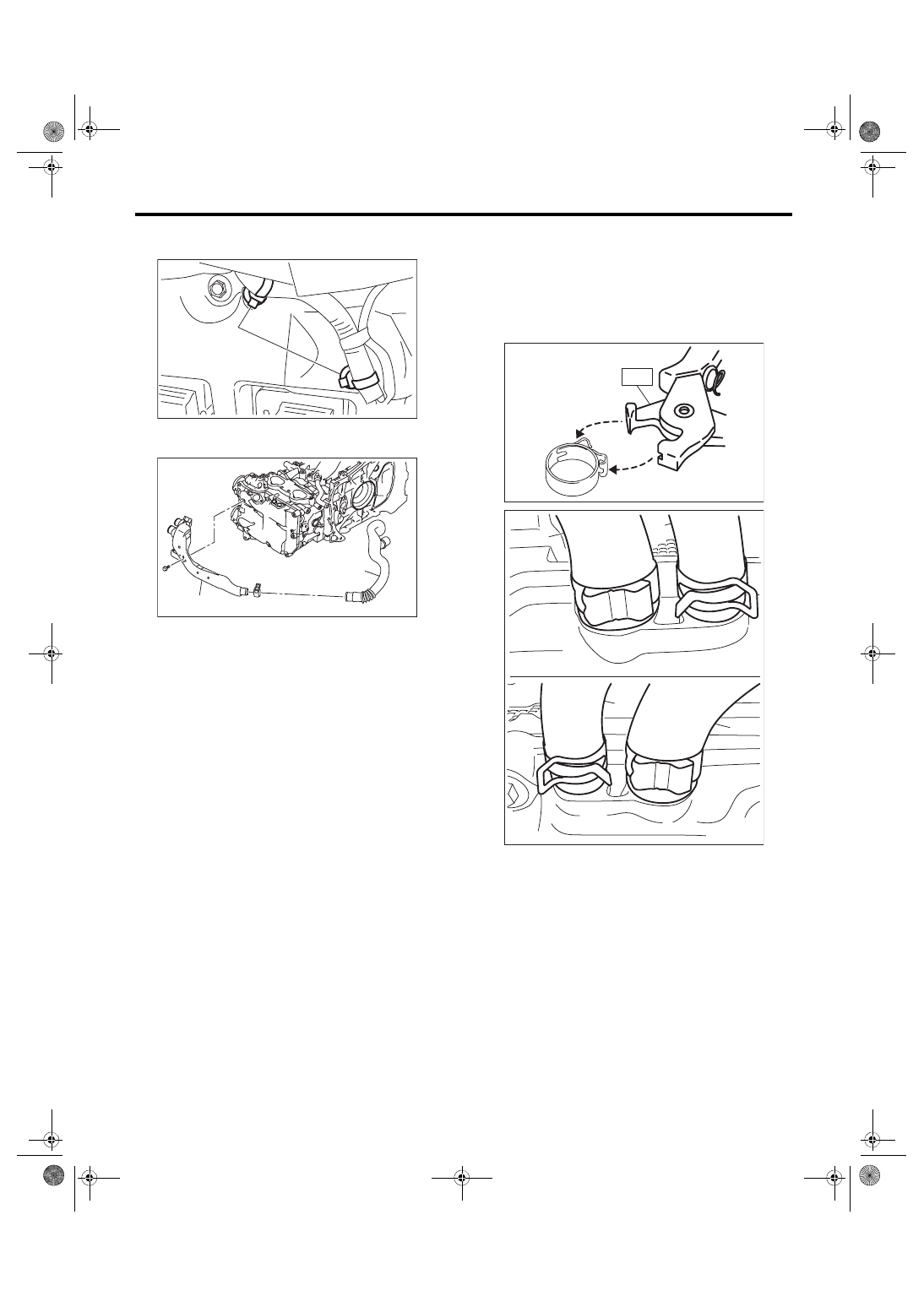
11) Remove the clip (A) which hold the engine har-

ness to the rocker cover RH.

12) Remove the air duct B (B) from the rocker cov-

er LH and the air duct A (A).

13) Remove  the  ignition  coil.  <Ref.  to  IG(STI)-7,

REMOVAL, Ignition Coil.>

14) Disconnect  PCV  hose  (A)  and  vacuum  hose

(B) from the rocker cover.
NOTE:

Pinch the clamp of the PCV hose (A) by fitting the

cut out in the ST with the protrusion on the clamp as

shown in the figure, and unlock the clamp.

ST 18353AA000 CLAMP PLIERS

15) Remove the rocker cover.

ME-05041

(A)

ME-04953

(B)

(A)

ME-04374

ST

ME-05768

(A)

(B)

(A)

(B)

ME(STI)-63

Camshaft

MECHANICAL

16) Remove  the  union  bolt  without  filter  (without

protrusion) which secures the oil pipe to the front

camshaft cap.

17) Loosen  the  upper  side  of  the  front  camshaft

cap and the intake camshaft cap bolts equally, a lit-

tle at a time in alphabetical sequence shown in the

figure.

18) Loosen the lower side of the front camshaft cap

and the exhaust camshaft cap bolts equally, a little

at a time in alphabetical sequence shown in the fig-

ure.

19) Remove the front camshaft cap.

20) Remove the intake camshaft caps and intake

camshaft.

(A) Union bolt with filter (with protrusion)
(B) Union bolt without filter (without protrusion)

(C) Oil pipe RH
(D) Oil pipe LH

(E) Gasket

ME-05030

(A)

(B)

(D)

(A)

(B)

(C)

(E)

(E)

(E)

(E)

(E)

ME-05978

(A)

(B)

(A)

(E)

(F)

(B)

(D)

(C)

(E)

(F)

(D)

(C)

ME-05979

(A)

(B)

(E)

(F)

(D)

(C)

(A)

(E)

(F)

(B)

(D)

(C)

ME(STI)-64

Camshaft

MECHANICAL

21) Remove  the  exhaust  camshaft  caps  and  ex-

haust camshaft.
NOTE:

Arrange camshaft caps in order so that they can be

installed in their original positions.

22) Remove the oil seal.
CAUTION:

Do not scratch the journal surface when remov-

ing the oil seal.

B: INSTALLATION

1) Install the camshaft.

Apply engine oil to the cylinder head at camshaft

journal  installation  location  before  installing  the

camshaft. Install the camshaft so that each valve is

close to or in contact with base circle of the cam

lobe.
NOTE:

• Set the camshaft to the position shown in the figure.

• When set at the position shown in the figure, it is

not necessary to rotate the camshaft RH when in-

stalling the timing belt, but it is necessary to rotate

the camshaft LH slightly.
Intake camshaft LH:

Rotate 80° clockwise.

Exhaust camshaft LH:

Rotate 45° counterclockwise.

2) Install the camshaft cap.

(1) Apply  small  amount  of  liquid  gasket  to  the

mating surface of cap.

NOTE:

• Install within 5 min. after applying liquid gasket.

• Do not apply liquid gasket excessively. Applying

excessively may cause excess gasket to come out

and flow toward oil seal, resulting in oil leak.
Liquid gasket:

THREE BOND 1217G (Part No. K0877Y0100) 

or equivalent

Liquid gasket applying diameter:

Mating surfaces other than ranges A and B

2

±

0.5 mm (0.0787

±

0.0197 in)

Mating surfaces of ranges A and B

3

±

1 mm (0.1181

±

0.0394 in)

(2) Apply  a  thin  coat  of  engine  oil  to  the  cap

journal surface, and install the camshaft cap to

the camshaft.

(A) Cylinder head RH
(B) Cylinder head LH

(a) Intake camshaft
(b) Exhaust camshaft

ME-05038

(B)

(A)

(a)

(b)

11

77.5

(b)

(a)

77.5

11

(A) Range A
(B) Range B

(C) Liquid gasket applying position of mating sur-

faces of ranges other than A and B

(D) Liquid gasket applying position of mating sur-

faces of ranges A and B

(E) 44.8 mm (1.7638 in)

(F) 65 mm (2.5591 in)

(G) φ2±0.5 mm (0.0787±0.0197 in)

(H) 0.5±0.5 mm (0.0197±0.0197 in)

(I) φ3±1 mm (0.1181±0.0394 in)

(J) 1 mm (0.0394 in) or less

ME-05769

(J)

(I)

(B)

(F)

A

A

B

B

B

(A)

(E)

A

A

B

B-B

(D)

A-A

(C)

(G)

(H)

ME(STI)-65

Camshaft

MECHANICAL

(3) Gradually  tighten  the  camshaft  cap  in  at

least two steps, in alphabetical order shown in

the  figure,  and  then  tighten  to  the  specified

torque.

Tightening torque:

T1: 9.75 N·m (1.0 kgf-m, 7.2 ft-lb)

T2: 20 N·m (2.0 kgf-m, 14.8 ft-lb)

(4) After  tightening  the  camshaft  cap,  ensure

the camshaft rotates only slightly while holding

it at base circle.

3) Apply a thin coat of engine oil to the periphery of

the camshaft oil seal and oil seal lip, and install the

oil seal on the camshaft using ST1 and ST2.
NOTE:

Use a new oil seal.

ST1 499587600

OIL SEAL INSTALLER

ST2 499597200

OIL SEAL GUIDE

4) Install the oil pipe to the front camshaft cap using

the union bolt without filter (without protrusion).
NOTE:

Use a new gasket.
Tightening torque:

29 N·m (3.0 kgf-m, 21.4 ft-lb)

5) Install the tensioner bracket.
Tightening torque:

24.5 N·m (2.5 kgf-m, 18.1 ft-lb)

ME-05980

(G)

(E)

(C)

(A)

(K)

(L)

(J)

(I)

(B)

(D)

(H)

(F)

(G)

(E)

(C)

(A)

(K)

(L)

(J)

(I)

(B)

(D)

(H)

(F)

T1

T2

T1

T2

T2

T2

T1

T1

ME-05002

ST1

ST2

(A) Union bolt with filter (with protrusion)
(B) Union bolt without filter (without protrusion)

(C) Oil pipe RH
(D) Oil pipe LH

(E) Gasket

ME-05033

(A)

(B)

(D)

(A)

(B)

(C)

(E)

(E)

(E)

(E)

(E)

ME-04984


Content   ..  73  74  75  76   ..