Subaru Impreza 3 / Impreza WRX / Impreza WRX STI. Manual - part 74
ME(STI)-58
Timing Belt
MECHANICAL
C: INSPECTION
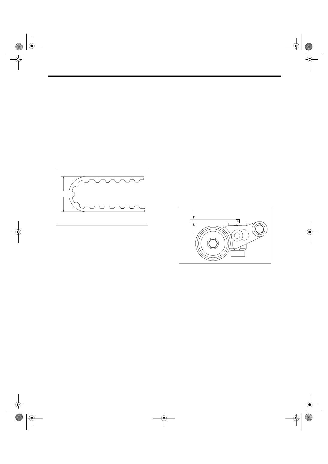
1. TIMING BELT
1) Check the timing belt teeth for breaks, cracks or
wear. If any fault is found, replace the timing belt.
2) Check the condition on the back surface of the
timing belt. If cracks are found, replace the timing
belt.
CAUTION:
• Be careful not to let oil, grease or coolant
contact the timing belt. Remove quickly and
thoroughly if this happens.
• Do not bend the timing belt sharply.
In radial diameter h:
60 mm (2.36 in) or more
2. AUTOMATIC BELT TENSION ADJUST-
ER
1) Visually check the oil seals for leaks, and rod
ends for abnormal wear and scratches. If neces-
sary, replace the automatic belt tension adjuster
assembly.
NOTE:
Slight traces of oil at the rod oil seal does not indi-
cate a problem.
2) Check that the adjuster rod does not move when
a pressure of 165 N (16.8 kgf, 37.1 lbf) is applied to
it. This is to check adjuster rod stiffness.
3) If the adjuster rod is not stiff enough and moves
freely when applying 165 N (16.8 kgf, 37.1 lbf),
check it using the following procedures:
(1) Slowly press the adjuster rod down to the
end surface of cylinder. Repeat this operation
two to three times.
(2) With the adjuster rod moved all the way up,
apply a pressure of 165 N (16.8 kgf, 37.1 lbf) to
it, and check the adjuster rod stiffness.
(3) If the adjuster rod is not stiff and moves
down, replace the automatic belt tension adjust-
er assembly with a new part.
CAUTION:
• Always use a vertical type pressing tool to
move the adjuster rod down.
• Do not use a lateral type vise.
• Push the adjuster rod vertically.
• Press-in the push adjuster rod gradually tak-
ing three minutes or more.
• Do not allow press pressure to exceed 9,807
N (1,000 kgf, 2,205 lbf).
• Push in the adjuster rod to the end face of the
cylinder. However, do not press the adjuster
rod below the end face of the cylinder. Doing so
may damage the cylinder.
4) Measure the amount of adjuster rod protrusion
“L” from the end surface of the cylinder. If it is not
within specifications, replace the automatic belt
tension adjuster assembly with a new part.
Protrusion amount of adjuster rod L:
5.2 — 6.2 mm (0.205 — 0.244 in)
3. BELT TENSION PULLEY
1) Check the mating surfaces of timing belt and
contact point of adjuster rod for abnormal wear or
scratches. Replace the automatic belt tension ad-
juster assembly with a new part if faulty.
2) Check the belt tension pulley for smooth rota-
tion. Replace the automatic belt tension adjuster
assembly with a new part if abnormal noise or ex-
cessive play occurs.
3) Check the belt tension pulley for grease leakage.
4. BELT IDLER
1) Check the belt idler for smooth rotation. Replace
if noise or excessive play occurs.
2) Check the outer contacting surfaces of idler pul-
ley for abnormal wear and scratches.
3) Check the belt idler for grease leakage.
ME-00248
h
ME-04106
L