Subaru Impreza 3 / Impreza WRX / Impreza WRX STI. Manual - part 72


  Index      Subaru     Subaru Impreza 3 / Impreza WRX / Impreza WRX STI - service repair manual 2008-2014 year


Search            


Content   ..  70  71  72  73   ..


Subaru Impreza 3 / Impreza WRX / Impreza WRX STI. Manual - part 72


ME(STI)-50

Timing Belt

MECHANICAL

15.Timing Belt

A: REMOVAL

NOTE:

• When replacing a single part, perform the work

with the engine assembly installed to body.

• When  performing  the  work  with  the  engine  in-

stalled to body, the following parts must also be re-

moved/installed.

• Radiator  main  fan  motor  assembly  <Ref.  to

CO(STI)-23, REMOVAL, Radiator Main Fan and

Fan  Motor.>  <Ref.  to  CO(STI)-23,  INSTALLA-

TION, Radiator Main Fan and Fan Motor.>

• Radiator  sub  fan  motor  assembly  <Ref.  to

CO(STI)-25, REMOVAL, Radiator Sub Fan and

Fan  Motor.>  <Ref.  to  CO(STI)-25,  INSTALLA-

TION, Radiator Sub Fan and Fan Motor.>

• When  performing  the  work  with  the  engine  in-

stalled to body, protect the radiator with cardboards

or blankets.

1. TIMING BELT

1) Remove the crank pulley. <Ref. to ME(STI)-47,

REMOVAL, Crank Pulley.>

2) Remove the timing belt cover. <Ref. to ME(STI)-

49, REMOVAL, Timing Belt Cover.>

3) Remove the timing belt guide.

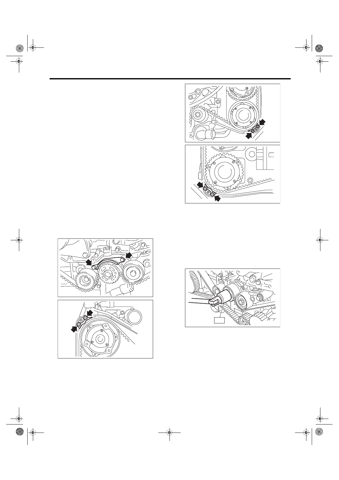
4) If the alignment mark or arrow mark (which indi-

cates the direction of rotation) on timing belt fade

away,  put  new  marks  before  removing  the  timing

belt as shown in procedures below.

(1) Turn the crankshaft using ST, and align the

alignment marks on crank sprocket, intake cam

sprocket LH, exhaust cam sprocket LH, intake

cam  sprocket  RH  and  exhaust  cam  sprocket

RH with marks on oil pump and notches of tim-

ing belt cover.

ST 499987500

CRANKSHAFT SOCKET

ME-00230

ME-03124

ME-03125

ME-03126

ME-00231

ST

ME(STI)-51

Timing Belt

MECHANICAL

(2) Using white paint, put an alignment mark or

an arrow mark on timing belts in relation to the

crank sprocket and cam sprockets.

Z

1

: 54.5 teeth

Z

2

: 51 teeth

Z

3

: 28 teeth

5) Remove the belt idler (A).

6) Remove the timing belt.
CAUTION:

After the timing belt has been removed, never

rotate  the  intake  and  exhaust  sprocket.  If  the

cam sprocket is rotated, the intake and exhaust

valve heads strike together and valve stems are

bent.

2. AUTOMATIC BELT TENSION ADJUST-

ER ASSEMBLY AND BELT IDLER

1) Remove the belt idler (A) and (B).

2) Remove the belt idler No. 2.

3) Remove the automatic belt tension adjuster as-

sembly.

ME-00070

ME-03127

ME-03128

Z

3

Z

1

Z

2

Z

3

(A)

ME-03935

(A)

(B)

ME-03936

ME-04977

ME-04978

ME(STI)-52

Timing Belt

MECHANICAL

B: INSTALLATION

1. AUTOMATIC BELT TENSION ADJUST-

ER ASSEMBLY AND BELT IDLER

1) Prepare for installation of the automatic belt ten-

sion adjuster assembly.
CAUTION:

• Always  use  a  vertical  type  pressing  tool  to

move the adjuster rod down.

• Do not use a lateral type vise.

• Push the adjuster rod vertically.

• Press-in the push adjuster rod gradually tak-

ing three minutes or more.

• Do not allow press pressure to exceed 9,807

N (1,000 kgf, 2,205 lbf).

• Push in the adjuster rod to the end face of the

cylinder.  However,  do  not  press  the  adjuster

rod below the end face of the cylinder. Doing so

may damage the cylinder.

• Do not release the press pressure until stop-

per pin is completely inserted.

(1) Attach  the  automatic  belt  tension  adjuster

assembly to vertical pressing tool.

(2) Slowly push in the adjuster rod with a pres-

sure of 165 N (16.8 kgf, 37.1 lbf) or more until

the adjuster rod is aligned with the stopper pin

hole in the cylinder.

(3) With a 2 mm (0.08 in) dia. stopper pin or a 2

mm (nominal) dia. hex wrench inserted into the

stopper pin hole in cylinder, secure the adjuster

rod.

2) Install the automatic belt tension adjuster assembly.
Tightening torque:

39 N·m (4.0 kgf-m, 28.8 ft-lb)

3) Install the belt idler No. 2.
Tightening torque:

39 N·m (4.0 kgf-m, 28.8 ft-lb)

4) Install the belt idlers.
Tightening torque:

39 N·m (4.0 kgf-m, 28.8 ft-lb)

Tightening torque:

25 N·m (2.5 kgf-m, 18.4 ft-lb)

ME-00239

ME-00350

ME-04979

ME-04977

ME-04980

ME-04981

ME(STI)-53

Timing Belt

MECHANICAL

2. TIMING BELT

1) Prepare for installation of the automatic belt ten-

sion adjuster assembly. <Ref. to ME(STI)-52, AU-

TOMATIC 

BELT 

TENSION 

ADJUSTER

ASSEMBLY  AND  BELT  IDLER,  INSTALLATION,

Timing Belt.>

2) Align  the  mark  (B)  on  crank  sprocket  with  the

mark (A) on oil pump.

3) Align the single line mark (B) on the exhaust cam

sprocket RH with notch (A) on the timing belt cover.

4) Align the single line mark (B) on the intake cam

sprocket RH with notch (A) on the timing belt cover.

Make sure that the double line marks (C) on intake

and exhaust cam sprockets are aligned.

5) Align  the  single  line  mark  (B)  on  exhaust  cam

sprocket LH with notch (A) on the timing belt cover

by  turning  the  sprocket  counterclockwise  (as

viewed from front of engine).

6) Align  the  single  line  mark  (B)  on  intake  cam

sprocket LH with notch (A) on the timing belt cover

by turning the sprocket clockwise (as viewed from

front of engine). Make sure the double line marks

(C) on the intake and exhaust cam sprockets are

aligned.

(B)

ME-04082

(A)

ME-04083

(A)

(B)

ME-04084

(A)

(C)

(B)

ME-04085

(A)

(B)

ME-04086

(B)

(A)

(C)


Content   ..  70  71  72  73   ..