Subaru Impreza 3 / Impreza WRX / Impreza WRX STI. Manual - part 71
ME(STI)-46
V-belt
MECHANICAL
C: INSPECTION
1. FRONT SIDE BELT
CAUTION:
Check and adjust the front side belt tension so
that it is within the specified range. Using the
belt with a tension out of the specified range
may result in a fault such as the following:
• If the front side belt tension is higher, unex-
pected force is generated at the power steering
oil pump, generator and crankshaft bearing,
causing abnormal noise due to abnormal wear
of the bearing.
• If the front side belt tension is lower, the front
side belt and crank pulley slip, causing abnor-
mally high temperature on the crank pulley due
to frictional heat. If this condition repeatedly
occurs, the front side belt may abnormally
wear, causing abnormal noise, front side belt
damage or crank pulley damage.
1) Replace the front side belt, if crack, fraying or
wear is found.
2) Check the front side belt tension and adjust it if
necessary by changing the generator installing po-
sition.
Front side belt tension (with belt tension
gauge):
When installing new parts
640 — 780 N (65 — 80 kgf, 144 — 175 lbf)
At inspection
490 — 640 N (50 — 65 kgf, 110 — 144 lbf)
Front side belt tension (without belt tension
gauge):
When installing new parts
7 — 9 mm (0.276 — 0.354 in)
At inspection
9 — 11 mm (0.354 — 0.433 in)
2. REAR SIDE BELT
Replace the rear side belt, if crack, fraying or wear
is found, or noise is emitted.
NOTE:
For the rear side belt, a stretch type belt is used,
and therefore, it is not necessary to check deflec-
tion nor tension.
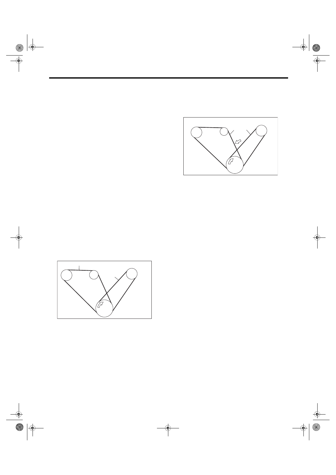
(A) Front side belt
(B) Rear side belt
C/P Crank pulley
GEN Generator pulley
P/S Power steering oil pump pulley
A/C A/C compressor pulley
ME-03313
C/P
P/S
A/C
GEN
(A)
(B)
(A) Front side belt
(B) Rear side belt
(C) 98 N (10 kgf, 22 lbf)
C/P Crank pulley
GEN Generator pulley
P/S Power steering oil pump pulley
A/C A/C compressor pulley
ME-03314
(A)
(B)
GEN
C/P
A/C
P/S
(C)