Subaru Legacy (2005 year). Manual - part 493
CS-13
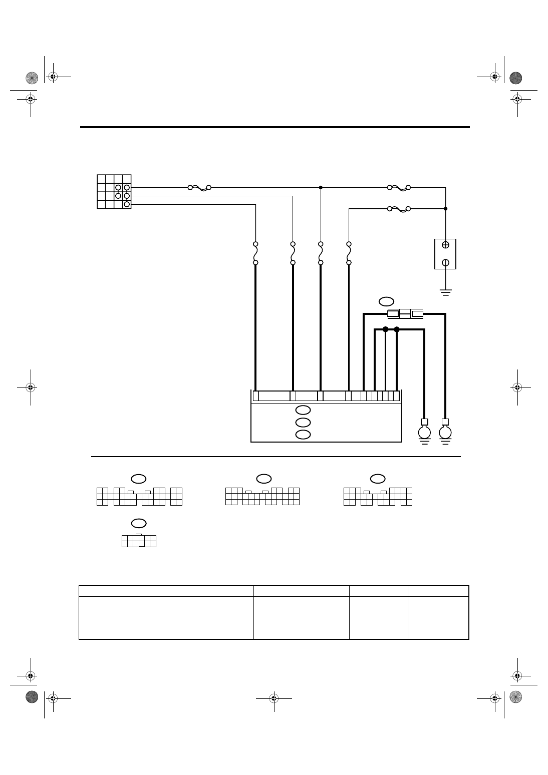
CONTROL SYSTEMS
AT Shift Lock Control System
2. BODY INTEGRATED MODULE POWER SUPPLY AND GROUND CIRCUIT
Step
Check
Yes
No
1
CHECK DTC OF BODY INTEGRATED MOD-
ULE.
Check DTC of body integrated module.
<Ref. to LAN(diag)-14, OPERATION, Subaru
Select Monitor.>
Is the DTC of power line dis-
played on body integrated
module?
Repair or replace it
according to the
DTC.
CS-00562
OFF ACC
ACC
ON
B
IG
MAIN SBF
SBF-8
No.12
B281
C:
B280
B:
A1
C2
C8
C9
E
No.7
B7
No.8
SBF-6
i84
A:
No.31
A24
B22
A21
5 6 7
8
2
1
9
4
3
10
24
22 23
25
11 12 13 14 15
26
27 28
16 17 18 19
20 21
5
4
6 7
8
2
1
9
3
10
22
23
11 12 13 14 15
24 25
26 27
16 17 18
28 29
19 20
21
30
1 2
3 4
5 6
7 8
9 10 11 12 13 14 15 16 17 18 19 20 21 22 23
24 25
26 27 28 29
30 31 32 33
34 35
B281
C:
B280
B:
i84
A:
IGNITION SWITCH
BATTERY
JOINT EARTH
CONNECTOR
BODY INTEGRATED MODULE
E
i97
1
2
i97
10 11 12
1 2 3 4 5 6
7 8 9