Subaru Legacy (2005 year). Manual - part 491


  Index      Subaru     Subaru Legacy - service repair manual 2005 year


Search            


Content   ..  489  490  491  492   ..


Subaru Legacy (2005 year). Manual - part 491


CS-5

CONTROL SYSTEMS

General Description

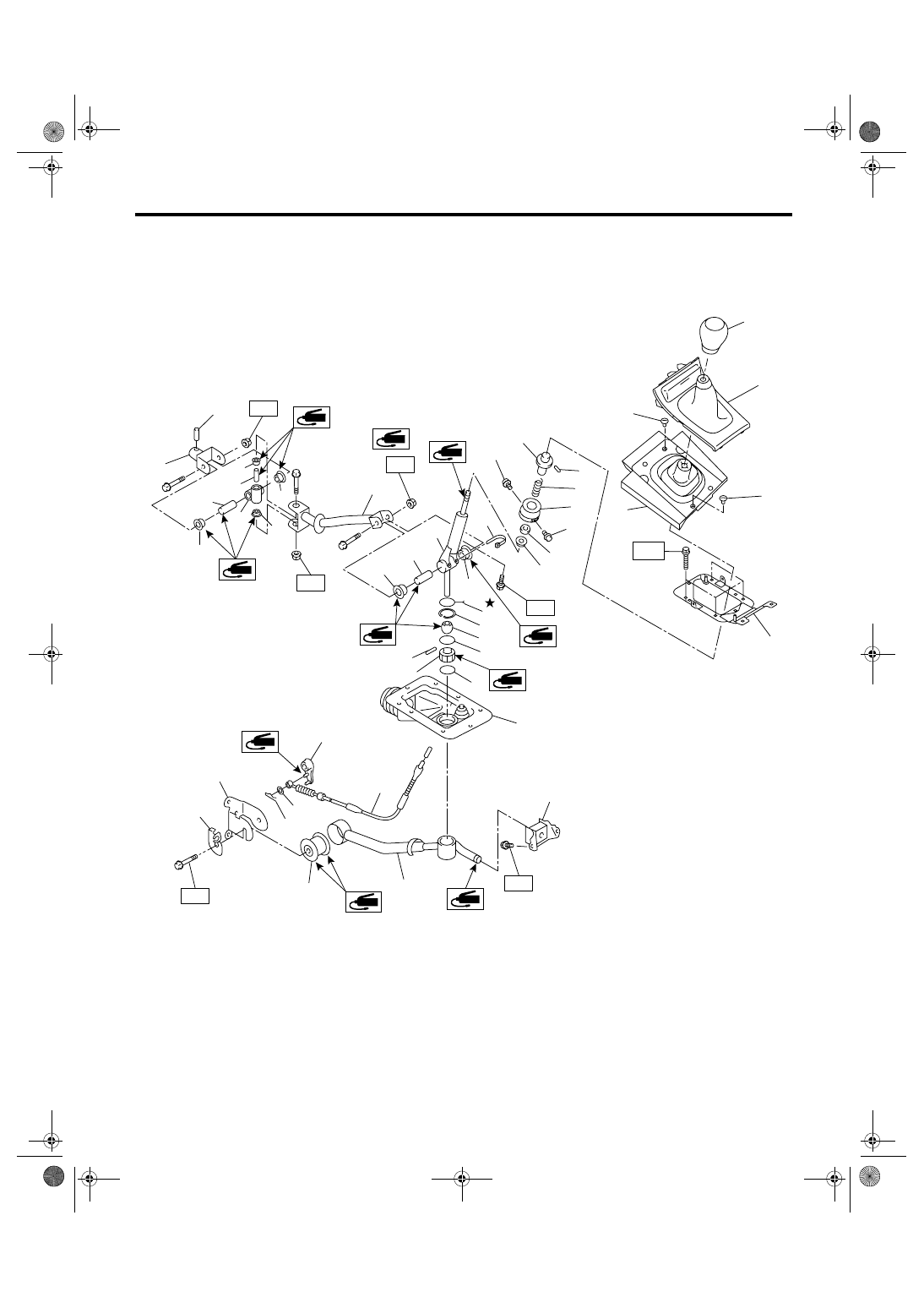
3. 6MT GEAR SHIFT LEVER

T4

T5

T3

(7)

(6)

(8)

(25)

(26)

(27)

(21)

(22)

(23)

(24)

(20)

(19)

(18)

T1

(15)

(17)

(16)

(14)

(13)

(12)

(30)

(31)

(12)

(11)

(10)

(9)

(29)

(28)

(13)

(13)

(33)

(12)

(12)

(12)

(12)

T3

T3

(34)

(36)

(37)

(36)

(35)

CS-00561

T4

(5)

(3)

(3)

(4)

(2)

(1)

(32)

CS-6

CONTROL SYSTEMS

General Description

4. DRIVE SELECT LEVER

(1)

Gear shift knob

(16)

Bushing

(31)

Reverse check lever

(2)

Front cover ASSY

(17)

Spring pin

(32)

Band clip

(3)

Clamp

(18)

Bushing

(33)

Boss

(4)

Boot and insulator ASSY

(19)

Boot

(34)

O-ring

(5)

Plate ASSY

(20)

Stay

(35)

O-ring

(6)

Slider

(21)

Cushion rubber

(36)

Screw

(7)

Spring pin

(22)

Bushing

(37)

Spring seat

(8)

Spring

(23)

Reverse check cable

(9)

Holder

(24)

Washer

Tightening torque: N

m (kgf-m, ft-lb)

(10)

Seat cushion

(25)

Snap pin

T1: 1.3 (0.13, 0.96)

(11)

Lever

(26)

Bracket

T2: 7.5 (0.76, 5.5)

(12)

Bushing

(27)

Cable plate

T3: 12 (1.2, 8.9)

(13)

Spacer

(28)

Joint

T4: 18 (1.8, 13.3)

(14)

Lock wire

(29)

Spring pin

T5: 32 (3.3, 23.6)

(15)

Snap ring

(30)

Rod

(1)

Cover

(7)

Plate ASSY

Tightening torque: N

m (kgf-m, ft-lb)

(2)

Knob

(8)

Bushing

T1: 4.5 (0.46, 3.3)

(3)

Lever ASSY

(9)

Clevis pin

T2: 12 (1.2, 8.9)

(4)

Bushing

(10)

Snap pin

T3: 27.5 (2.80, 20.3)

(5)

Spacer

(11)

Cable

(6)

Spring

(12)

Clip

CS-00371

(10)

(11)

(12)

(4)

(4)

(3)

(7)

T2

T2

T2

T1

T1

T3

(8)

(9)

(5)

(1)

(2)

(6)

CS-7

CONTROL SYSTEMS

General Description

C: PREPARATION TOOL

1. SPECIAL TOOL

D: CAUTION

• Wear work clothing, including a cap, protective
goggles, and protective shoes during operation.
• Remove contamination including dirt and corro-
sion before removal, installation or disassembly.
• Keep the disassembled parts in order and pro-
tect them from dust and dirt.
• Before removal, installation or disassembly, be
sure to clarify the failure. Avoid unnecessary re-
moval, installation, disassembly and replacement.
• Use SUBARU genuine fluid, grease etc. or
equivalent. Do not mix fluid, grease, etc. with that of
another grade or from other manufacturers.
• Be sure to tighten fasteners including bolts and
nuts to the specified torque.
• Place shop jacks or rigid racks at the specified
points.
• Apply grease onto sliding or revolution surfaces
before installation.
• Before installing O-rings or snap rings, apply suf-
ficient amount of fluid to avoid damage and defor-
mation.
• Before securing a part in a vice, place cushioning
material such as wood blocks, aluminum plate, or
cloth between the part and vice.
• Before disconnecting electrical connectors, be
sure to disconnect the ground cable from battery.

ILLUSTRATION

TOOL NUMBER

DESCRIPTION

REMARKS

18482AA000

(Newly adopted tool)

CARTRIDGE

Troubleshooting for electrical system.

22771AA030

SUBARU SELECT 
MONITOR KIT

Troubleshooting for electrical system.
• English: 22771AA030 (Without printer)
• German: 22771AA070 (Without printer)
• French: 22771AA080 (Without printer)
• Spanish: 22771AA090 (Without printer)

ST18482AA000

ST22771AA030

CS-8

CONTROL SYSTEMS

AT Shift Lock Control System

2. AT Shift Lock Control System

A: LOCATION

(1)

TCM (“P” range)

(4)

Key cylinder (with built-in key 
warning switch)

(6)

“P” range switch

(2)

Body integrated module

(7)

Key lock solenoid

(3)

Stop light switch

(5)

Shift lock solenoid unit

CS-00513

(1)

(3)

(2)

(5)

(6)

(7)

(4)

CS-00514

(1)

CS-00515

(2)


Content   ..  489  490  491  492   ..