SsangYong Musso. Manual - part 389


  Index      SsangYong     SsangYong Musso - service repair manual


Search            


Content   ..  387  388  389  390   ..


SsangYong Musso. Manual - part 389


1B3-118  OM600 ENGINE MECHANICAL

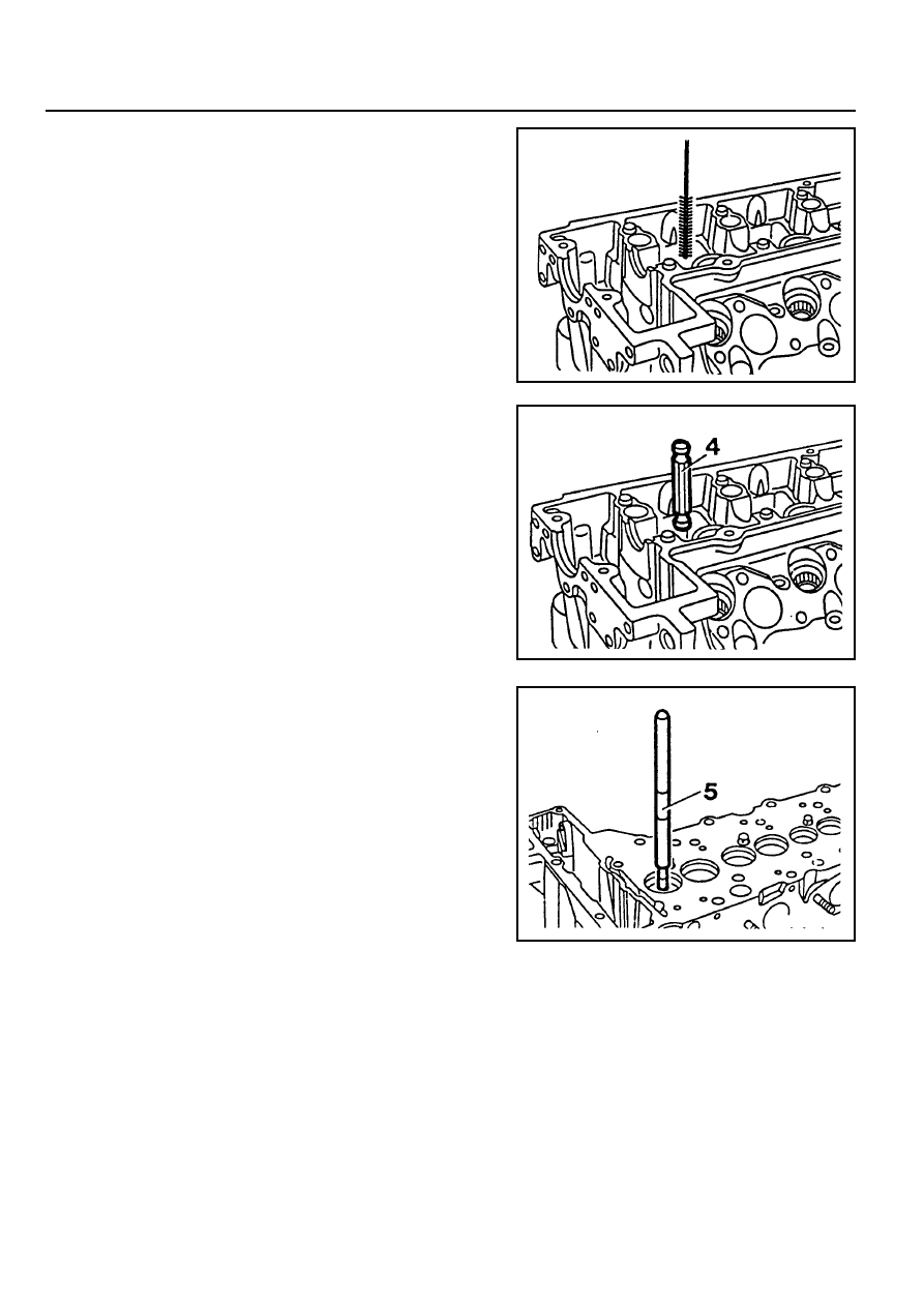
2. Thoroughly clean the basic bore by using a cylinder brush.

Cylinder Brush 000 589 10 68 00

3. Check the basic bore in cylinder head for scoring marks

and ream to next repair size if necessary.

2. Insert the GO/NO GO gauge into the valve guide bore. If

the NO GO side is inserted fully, replace the valve guide
(Intake 8mm, Exhaust 9mm).

GO/NO GO Gauge 601 589 02 23 00

Replacement Procedure

1. Drive out the valve guide (2) by using a drift (5).

Notice

The valve guide must be driven out upward of the cylinder
head.

Drift (for Intake) 103 589 03 15 00

Drift (for Exhaust) 103 589 02 15 00

Checking

1. Thoroughly clean the valve guide bore using a cylinder

brush.

Cylinder Brush 000 589 10 68 00

OM600 ENGINE MECHANICAL  1B3-119

4. Reaming basic bore in cylinder head (repair size).

- Thoroughly remove carbon deposits in cylinder head.

Notice

Particularly remove the insides of the valve seat rings.

- Remove the elevation (arrow) of intake valve seat rings.

- Select correct broaching tool and guide sleeve (refer to

the table).

Notice

Before broaching work, the broaching tool must be cleared
of swarf with a stiff plastic brush.

- Lubricate the basic bore, guide sleeve and broaching tool

with petroleum.

- Push broaching tool (6) in broaching direction (arrow) into

the guide sleeve (7) far enough so that the first cut of the
broaching tool is positioned in the basic bore when guide
sleeve is fitted onto the valve seat ring (3).

6. Broaching tool

7. Guide sleeve

See the ‘standard data’

- Center the guide sleeve (7) in the valve seat ring (3) by

turning.

- Knock through the broaching tool (6) with a plastic hammer

(approx. 25g). and aluminum drift.

1B3-120  OM600 ENGINE MECHANICAL

8. Check the valve guide bore with GO / NO GO gauge (9).

The GO side (marked ‘0’) should just still drop. If the GO
side cannot be inserted, the bore of valve guide should be
reamed.

Notice

Perform the check only on cooled down cylinder head.

GO / NO GO Gauge (for Intake) 102 589 00 23 00

GO / NO GO Gauge (for Exhaust) 117 589 03 23 00

6. Cool down the new valve guide (2) with liquid nitrogen.

Notice

Do not touch the cooled valve guide by hand.

Super Cooling box 346 589 00 63 00

7. Drive in new valve guide with drift (8) until the wire ring makes

contact.

Notice

The valve guide must be driven in from the cylinder head
cover.

Drift (for Intake) 601 589 05 15 00

Drift (for Exhaust) 601 589 06 15 00

5. Heat the cylinder head (1) in a wear tank to approx. 80°C.

OM600 ENGINE MECHANICAL  1B3-121

9. If necessary, ream the valve guide bore evenly.

Notice

Never turn the reamer against the direction of rotation.

Reamer (for Exhaust)  000 589 10 53 00

Reamer (for Intake)  000 589 21 53 00


Content   ..  387  388  389  390   ..