SsangYong Musso. Manual - part 390


  Index      SsangYong     SsangYong Musso - service repair manual


Search            


Content   ..  388  389  390  391   ..


SsangYong Musso. Manual - part 390


1B3-122  OM600 ENGINE MECHANICAL
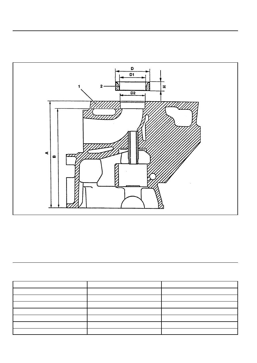
VALVE SEAT RINGS

Preceding Work   : Removal of valve

Checking of valve guide, replace if necessary
Removal of prechamber

1 Cylinder Head
2 Valve Seat Ring
3 Valve Guide

A Height (Cylinder Head Upper / Lower Surface)
B Height (cylinder Head Cover Surface - Seat of

Valve Seat Ring)

D

Valve Seat Ring Outer Diameter

D1 Valve Seat Ring Inner Diameter
D2 Basic Bore Diameter
H

Height of Valve Seat Ring

Service Data

Item

D2

D

D1

H

Overlap U=D-D2

B

A

Intake

40.000 - 40.016mm

40.084 - 40.100mm

33.400 - 33.600mm

6.955 - 7.045mm

0.068 - 0.100mm

133.4mm

142.5mm

Exhaust

37.000 - 37.016mm

37.084 - 37.100mm

30.400 - 30.600mm

6.955 - 7.045mm

0.068 - 0.100mm

133.4mm

142.5mm

OM600 ENGINE MECHANICAL  1B3-123

Cylinder Head Clamping Device

Valve Seat Turning Tool

Ring Seat Turning Tool

Pneumatic Removal / Installation Device

(Drift : 8mm, 9mm, 14mm)

Tensioning Head

Cutting Tool for Recessing Grooves

Test Set for Valves

Internal Dial Gauge (Range : 25 - 60mm)

External Micrometer (Range : 25 - 60mm)

Electrically Heated Water Tank

Commercial Tools

Hunger

D-8000 München 70

Type Ventilknecht K2000

Order No. 221 00 100

Hunger

D-8000 München 70

Type VDS 1A

Order No. 236 03 308

Hunger

D-8000 München 70

Type RDS 1

Order No. 219 00 100

Hunger

D-8000 München 70

Type PVM 1

Hunger

D-8000 München 70

Order No. 250 15 250

Hunger

D-8000 München 70

Order No. 217 93 601

Hunger

D-8000 München 70

Order No. 216 69 210

Mahr

D-7300 Esslingen

Order No. 844

Mahr

D-7300 Esslingen

Order No. 40 S

Otto Dürr

D-7123 Sachsenherm - Ochsenbach

1B3-124  OM600 ENGINE MECHANICAL

1. Measure dimension ‘A’.

Removal Procedure

Limit

142.5mm

2. Clamp the cylinder head with clamping device.

3. Cut groove into the valve seat ring so that dimension ‘C’ is

approx. 2mm and dimension ‘E’ is approx. 6mm.

4. Remove the cylinder head from the clamping device and

place it onto wooden blocks.

5. Remove the valve guide (3).

Drift (Intake) 8mm

Drift (Exhaust) 9mm

6. Insert the tensioning head (4) and extracted wedges(arrow)

by turning the bolt (5).

Notice

Carefully tighten the bolt (5) otherwise the valve seat ring in
the cylinder head will be excessively tensioned.

7. Lock the bolt (5) with nut (6).

OM600 ENGINE MECHANICAL  1B3-125

8. Turn over the cylinder head.

9. Remove the tensioning head (4) and valve seat ring (2)

with drift (14mm) and removal tool.

10. Clean the basic bore of valve seat ring.

11. Measure the basic bore diameter (D2) and outer diameter

(D) of the new valve seat ring (standard size).

12. Calculate the overlap value ‘U’ (D - D2).

Overlap Value ‘U’

0.068 - 0.100mm

Example)

Measured value D   = 37.100mm

Measured value D2 = 37.010mm

Overlap value ‘U’     =    0.090mm

If overlap value ‘U’ is out of standard, machine

the basic bore for the valve seat ring.

13. Clamp the cylinder head with clamping device.

14. Machining basic bore for valve seat ring (repair size).

Notice

Maintain minimum value of ‘B’.

- Machine the basic bore.

       Limit

Intake

Exhaust

Max. D2

Min. B

40.516mm

37.516mm

133.4mm

- Measure machined basic bore and outer diameter ‘D’

of valve seat ring (repair size).

- Measure the overlap ‘U’

Overlap ‘U’ (D - D2)

0.068 - 0.100 mm

       Example)

Measured value D   = 37.600 mm

Measured value D2 = 37.480 mm

Overlap

U   =   0.120 mm

The basic diameter D2 must be machined by

0.020mm in order to get the required overlap

value.


Content   ..  388  389  390  391   ..