Scania DI13 PDE. Marine engine en-GB 2 805 601. Operator’s manual - part 4
Cooling system
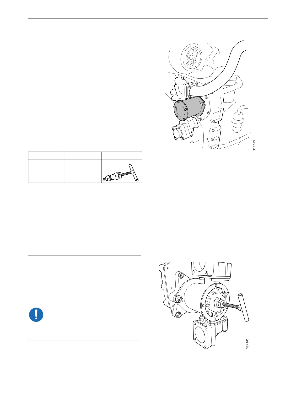
Checking the sea water pump
impeller
1. Drain the sea water circuit as described in the
Draining the sea water circuit section.
2. Remove the sea water pump cover. See illus-
tration.
3. Check that the vanes of the impeller are not
heavily splintered or damaged.
Renewing the sea water pump impel-
ler
Special tools
Number
Designation
Illustration
98 482
Puller
Note:
If the impeller must be renewed frequently, the
cleaning of the sea water needs to be improved.
There should be a spare impeller and puller on
board.
The impeller can be deformed during extended
periods of inactivity. Renew the impeller before
starting or remove the impeller before longer pe-
riods of stoppage.
1. Pull out the impeller using the puller. Note
the direction of rotation of the impeller
vanes.
2. Fit a new impeller and cap. Check that the
cap seal is not hard or damaged.
IMPORTANT!
When fitting the new impeller, bend the vanes in
the same direction as on the old one.
48
Cooling system
Changing the coolant and
cleaning the cooling system
Draining coolant
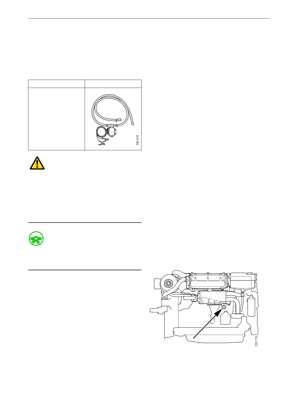
Special tools
Number, designation
Illustration
2 443 679, coolant
pump
WARNING!
Do not open the coolant filler cap in the expan-
sion tank if the engine is hot. Hot coolant and
steam may spray out and cause burns. If the cap
has to be opened do it slowly to release the pres-
sure before removing the cap.
Use protective gloves as coolant can cause irrita-
tion if it comes in contact with the skin.
Environment
Use a suitable container. Used coolant must be
disposed of as specified in national and interna-
tional laws and regulations.
1. Open the expansion tank cap.
2. Position the hose from the coolant pump in
an empty container.
3. Connect the pump to the draining nipple in
the cylinder block. See illustration.
4. Connect the pump's 2 cable terminals to the
battery's negative and positive terminal.
Make sure that the drainage starts. If the
drainage does not start: Change the position
of the cable terminals.
5. Repeat the procedure at the cooling system's
Drain nipple in the cylinder block.
lowest drainage point. The location of the
lowest drainage point on the engine may dif-
fer depending on engine application.
49
Cooling system
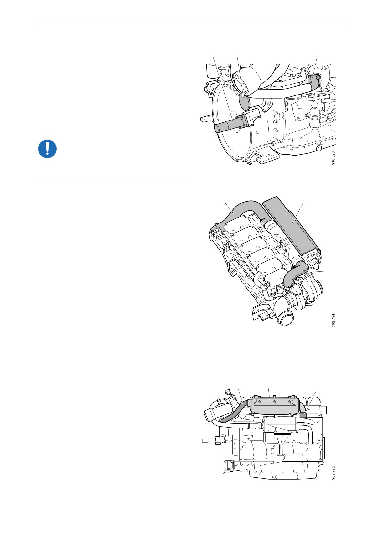
Draining the sea water circuit
3
2
1
1. Close the bottom valve on the sea water inlet
and remove the connection pipe (1) on the
outlet from the heat exchanger.
2. Remove the cover (2) from the sea water
pump to empty the pump completely.
The lowest point in the sea water circuit may be
at different points, but it is usually in the sea wa-
ter pump intake (3).
IMPORTANT!
Plug the connections to prevent dirt ingress into
the engine.
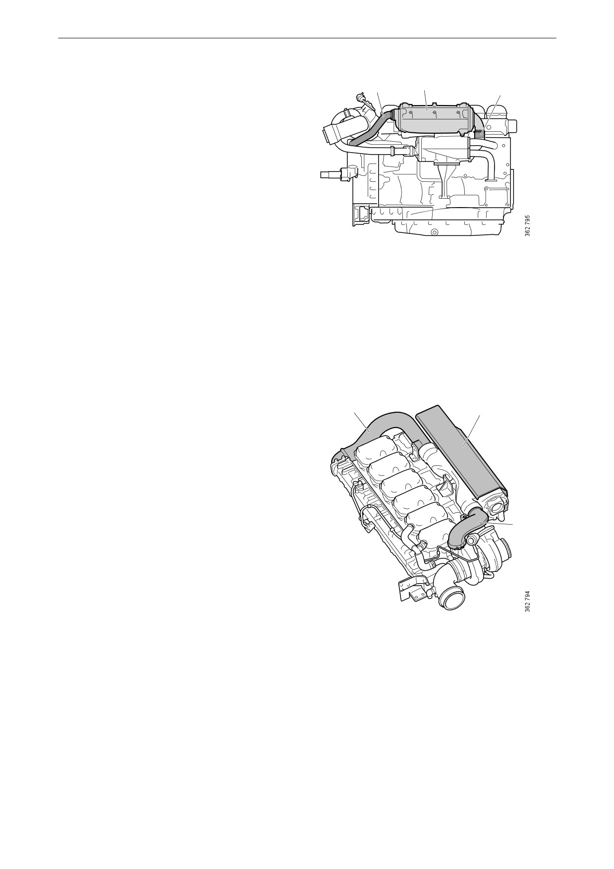
Removing the charge air cooler
3
1
When the cooler core of the charge air cooler
needs cleaning, the charge air cooler must be re-
moved if there is no space behind it to take out
the cooler core.
Before starting work: Make sure that the cooling
system is empty as described earlier.
1. Remove the protective plate (1) on the
2
charge air cooler.
2. Remove the charge air pipe (2) between the
charge air cooler and the turbocharger. Twist
the pipe to facilitate removal.
If the turbocharger has a wastegate valve and
the charge air pipe must be removed, the pipe
bracket must be removed and the pipe must
be turned 90° upwards before the hose and
the pipe are removed.
3. Remove the charge air pipe (3) between the
charge air cooler and the inlet pipe.
4. Remove the water pipe (4) of the charge air
cooler.
4
6
5
5. Release the hose clamp and remove the sea
water hose (5) between the charge air cooler
and the heat exchanger.
6. Remove the charge air cooler (6).
50
Cooling system
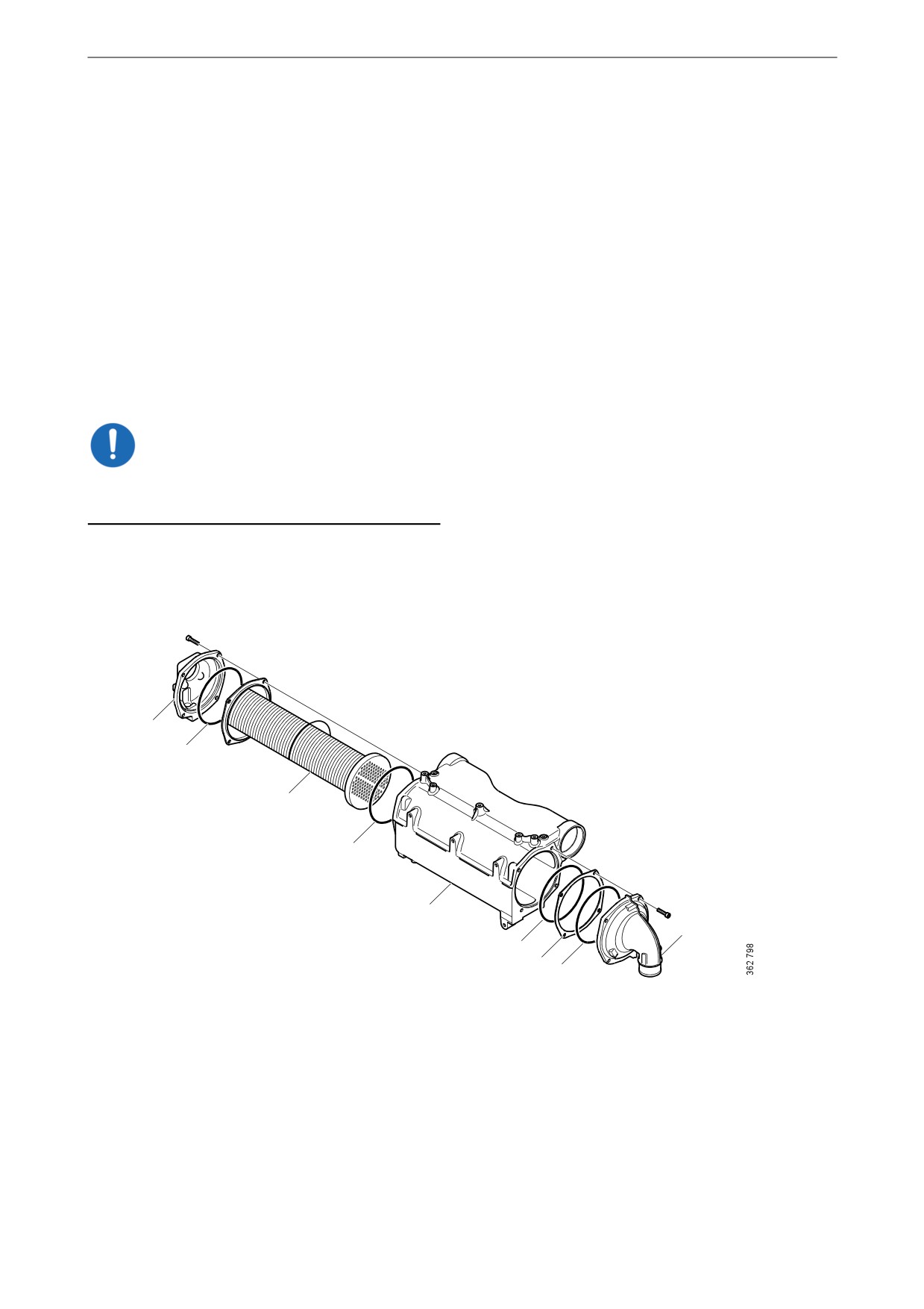
Cleaning the charge air cooler
The charge air cooler must be removed if there is
no space behind it to take out the cooler core. See
previous section.
1. Remove the screws on the charge air cooler
covers (1) and remove the covers. Mark the
covers so that you can put them back on the
correct side.
2. Press in the cooler core (3) slightly on one
side and pull it out from the other side.
3. Clean the cooler core on the outside with par-
affin-based engine detergent. Remove any
internal deposits using a round rod. Renew
the cooler core if it is damaged.
IMPORTANT!
Do not use caustic soda as this could damage the
aluminium.
4. Renew damaged or hard O-rings (2).
5. Assemble the charge air cooler. Tighten the
M8 screws on the covers to 15 Nm (11 lb-ft).
1
2
3
2
4
1
2
5
2
1. Cover.
2. O-rings.
3. Cooler core.
4. Charge air cooler housing.
5. Spacer.
51
Cooling system
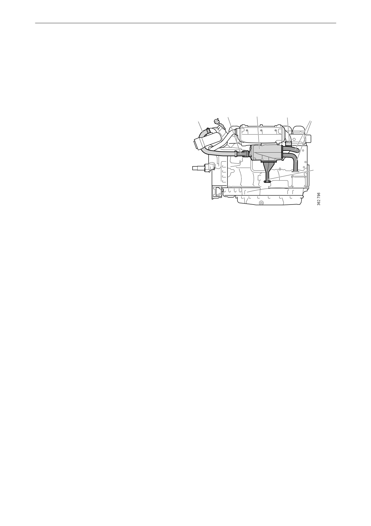
Removing the heat exchanger
When the cooler core of the heat exchanger
needs cleaning, the heat exchanger must be re-
moved.
Before starting work: Make sure that the cooling
system is empty as described earlier.
1. Undo the V-clamp for the hose (1) between
2
4
3
the heat exchanger and the water-cooled ex-
2
1
haust pipe bend, if the engine has one. Bend
the hose to one side.
2. Remove the inlet and outlet coolant pipes
and the sea water pipe (2) from the heat ex-
changer.
3. Release the hose clamp and remove the sea
5
water hose (3) between the charge air cooler
and the heat exchanger.
4. Remove the screws holding the heat ex-
changer (4) in the two brackets.
5. Slacken the screws holding the heat ex-
changer bracket (5) in the cylinder block suf-
ficiently to allow the heat exchanger to be
removed.
6. Remove the heat exchanger.
52
Cooling system
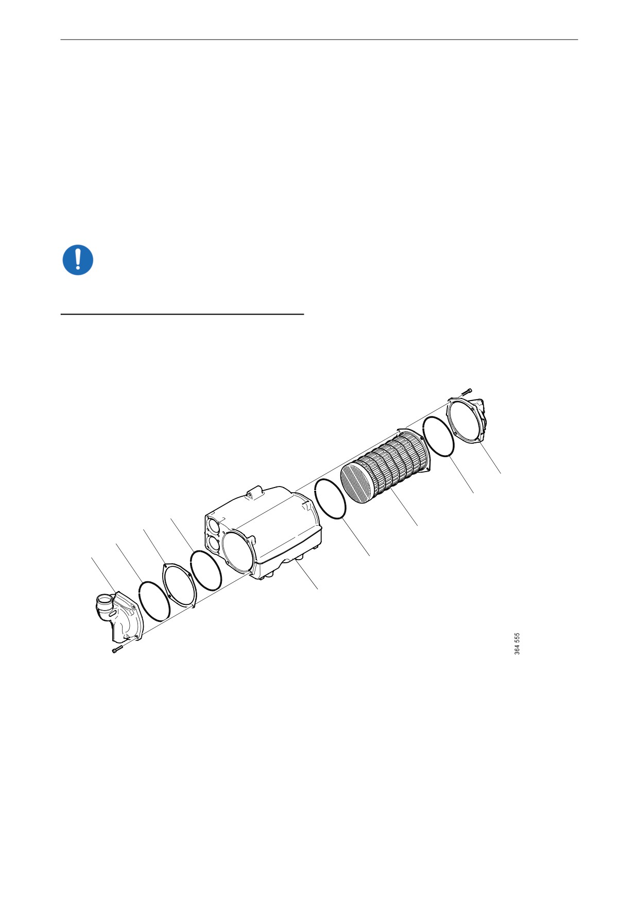
Cleaning the heat exchanger
1. Remove the screws on the heat exchanger
covers (1) and remove the covers. Mark the
covers so that you can put them back on the
correct side.
2. Press in the cooler core (5) slightly on one
side and pull it out from the other side.
3. Clean the cooler core on the outside with par-
affin-based engine detergent. Remove any
internal deposits using a round rod. Renew
the cooler core if it is damaged.
IMPORTANT!
Do not use caustic soda as this could damage the
aluminium.
4. Renew damaged or hard O-rings (2).
5. Assemble the heat exchanger. Tighten the
M8 screws on the covers to 15 Nm (11 lb-ft).
1
2
2
3
5
2
1
2
4
1. Cover.
2. O-rings.
3. Spacer.
4. Heat exchanger housing.
5. Cooler core.
53
Cooling system
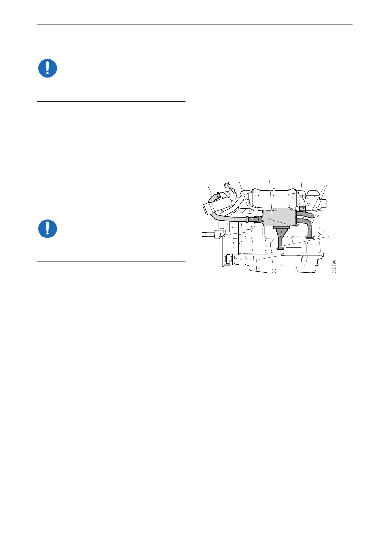
Fitting the heat exchanger
IMPORTANT!
There is a risk that the joint will crack if these in-
stallation instructions are not followed.
Tightening torques
M6
10 Nm (7 lb-ft)
M8
26 Nm (19 lb-ft)
M10
50 Nm (37 lb-ft)
1. Fit the heat exchanger (4) in place against the
2
4
3
brackets.
2
1
2. Fit the sea water hose (3) between the heat
exchanger and charge air cooler (use vase-
line if necessary) and tighten the hose clamp.
IMPORTANT!
5
To prevent leakage, a hose clamp with a safety
ring can be used.
3. Fit the screws (5 off) securing the heat ex-
changer without tightening them.
4. Tighten the screws securing the heat ex-
changer bracket (5) in the cylinder block.
5. First tighten the screw on the charge air cool-
er bracket and then the 4 screws on the heat
exchanger bracket.
6. Fit the inlet and outlet coolant pipes and the
sea water pipe from the heat exchanger (2).
7. Fit the hose (1) between the heat exchanger
and the water-cooled exhaust pipe bend and
tighten the V-clamp.
54
Cooling system
Fitting the charge air cooler
4
6
5
Tightening torques
M6
10 Nm (7 lb-ft)
M8
26 Nm (19 lb-ft)
M10
50 Nm (37 lb-ft)
1. Fit the charge air cooler (6) in place against
the brackets.
2. Fit the sea water hose (5) between the charge
air cooler and heat exchanger (use vaseline if
necessary) and tighten the hose clamp.
3. Fit the screws for the charge air cooler brack-
ets and tighten them.
4. Fit the water pipe (4) between the water
pump and the charge air cooler.
5. Fit the charge air pipe (3) between the intake
manifold and charge air cooler. To facilitate
fitting, lubricate the O-ring and the inside of
the connection in the charge air cooler with
vaseline. Press the charge air pipe straight to-
wards the charge air cooler while carefully
twisting the pipe to the right and left. Check
that the charge air pipe is properly fitted.
3
1
6. Fit the charge air pipe (2) between the charge
air cooler and turbocharger. To facilitate fit-
ting, lubricate the O-ring and the inside of the
connection in the charge air cooler with
vaseline. Press the charge air pipe straight to-
wards the charge air cooler while carefully
twisting the pipe to the right and left. Check
that the charge air pipe is properly fitted.
7. Fit the protective plate (1) on the charge air
2
cooler.
55
Cooling system
Internal cleaning: Removing oil and
3. Fill the cooling system with clean hot water
grease in the cooling system
mixed with detergent 2 479 017. Detergent
2 479 017 must make up 5-10% (depending
on the degree of dirt) of the total coolant vol-
Environment
ume.
Use a suitable container. Used coolant must be
If detergent 2 479 017 is not available, use a
disposed of as specified in national and interna-
dishwasher detergent for household dish-
tional laws and regulations.
washers that does not foam. Concentration
1%.
4. Run the engine until it has reached operating
Always fit a new thermostat and a new cover to
temperature for approximately 20-30 min-
the expansion tank after cleaning, as the oil in the
utes. Remember to switch on the cab heating
cooling system destroys the seals. If the engine is
system, if one is installed.
equipped with a coolant filter, also renew this fil-
5. Drain the cooling system.
ter.
6. Fill the cooling system with clean, hot water
It may be necessary to wash it multiple times if
and run the engine for about 20-30 minutes.
the cooling system is very dirty. One cause of
7. Repeat steps 3-6 if the cooling system is not
contamination can be that oil is lying on top of
clean.
the coolant and collecting high up in the cooling
system. If several rinses are needed, this is not
8. Drain the water from the cooling system.
necessarily because work has been carried out
9. If necessary, clean the expansion tank by de-
incorrectly. Oil residues often need to be rinsed
taching all hoses and rinsing and cleaning
repeatedly from the expansion tank and the ex-
with a degreasing agent and a dishwashing
ternal heating system to be completely clean.
brush.
Repeated washing is more effective and prefera-
Alternatively, dismantle the expansion tank
ble to using higher concentrations of detergent
and clean it with water with 10% of detergent
(max. 10%) or cleaning for a longer period (max
2 479 017. Fill the expansion tank with the
30 minutes).
mixture, shake it and drain it. Renew the cov-
er of the expansion tank.
If only a small amount of dirt has collected in the
10. Fit a new thermostat.
expansion tank after cleaning, one extra rinse
and clean of the expansion tank only is usually
11. Fill the cooling system with new coolant as
sufficient. There is no need to clean the whole
described in the next section.
cooling system again.
12. Check again whether further dirt or oil has
collected in the expansion tank. Decide
1. Run the engine until it has reached operating
whether it it is necessary to carry out another
temperature and then drain the cooling sys-
full cleaning or whether only rinsing or
tem following the previous description.
cleaning of the expansion tank will suffice.
2. Remove the thermostat.
56
Cooling system
Internal cleaning: Removing deposits
in the cooling system
Environment
Use a suitable container. Used coolant must be
disposed of as specified in national and interna-
tional laws and regulations.
1. Run the engine until it has reached operating
temperature and then drain the cooling sys-
tem following the previous description.
2. Remove the thermostat.
3. Fill the cooling system with clean, hot water
mixed with radiator detergent which is based
on sulphamic acid and contains dispersing
agents. Follow the manufacturer's instruc-
tions for the concentration and cleaning peri-
od.
4. Run the engine for the specified time. Re-
member to switch on the cab heating system,
if one is installed.
5. Drain the cooling system.
6. Fill the cooling system with clean, hot water
and run the engine for about 20-30 minutes.
7. Drain the water from the cooling system.
8. Reinstall the thermostat.
9. Fill the cooling system with new coolant as
described in the next section.
57

Cooling system
Filling coolant
This procedure applies when the cooling system
has been drained and needs to be filled with a
large amount of coolant.
Special tools
Number, designation
Illustration
2 443 679, coolant
pump
WARNING!
Use protective gloves as coolant can cause irrita-
tion if it comes in contact with the skin. Hot cool-
ant can also cause scalding.
IMPORTANT!
Mix the coolant as specified in the section head-
ed Coolant.
It is not permissible to top up large amounts of
coolant via the expansion tank. Filling via the ex-
pansion tank leads to air locks in the cooling sys-
tem which can lead to e.g. damage to the coolant
pump shaft seal.
Never fill a large amount of cold coolant in a hot
engine. There is great risk of cracks forming in
the cylinder block and cylinder heads.
Do not start the engine until the correct coolant
level has been obtained. If the engine is started
with an insufficient coolant level, it can damage
the coolant pump shaft seal, which leads to cool-
ant leakage.
58

Cooling system
1. Open the expansion tank cap.
2. Connect the coolant pump to the filler nipple
in the cylinder block.
3. Connect the pump's 2 cable terminals to the
battery's negative and positive terminal.
Make sure that the filling starts. If the filling
does not start: Change the position of the ca-
ble terminals.
4. Start the engine and run it at idling for
15 minutes.
IMPORTANT!
Filler nipple in the cylinder block.
It is very important that the engine is idling. En-
gine overspeed could damage the coolant pump
shaft seal, which leads to coolant leakage.
5. Switch off the engine and fill with coolant to
the maximum level through the expansion
tank.
Air pockets may still be left in the cooling
system. These will disappear after the engine
has been operated for a period of time.
Therefore, the coolant may need topping up
at a later stage.
Finishing operations
1. Open the bottom valve on the sea water inlet.
2. Start the engine and check that no leakage
occurs.
3. Check the coolant level and top up the cool-
ant via the expansion tank if necessary.
59
Fuel system
Fuel system
Cleanliness requirements
IMPORTANT!
The whole fuel system is very sensitive to dirt
and even very small particles. Foreign particles
in the system can cause serious malfunctions. It
is therefore very important that everything is as
clean as possible when work is carried out on the
fuel system. Before repair work, the engine must
be washed. If possible, a hot water wash should
be used.
It is strictly forbidden to carry out any machining
work or work with compressed air near an open
fuel system.
Be extra careful and always use clean, lint-free
and dust-free clothes and disposable gloves
when working on the fuel system. Scania recom-
mends using Tegera 848 gloves.
Clean tools before they are used and do not use
any worn or chrome-plated tools. Material and
flakes of chrome may come off.
Clean connections and the surrounding area be-
fore removal. When cleaning, cloths or paper
which shed fibres must not be used. Use clean
and lint free cloths, part number 588 879.
Plug or cover the connections during removal.
Also clean the connections before the compo-
nents are fitted. Place removed components on a
thoroughly cleaned, dust-free surface. Scania
recommends using a stainless steel bench top,
part number 2 403 296. Cover the components
with a lint free cloth.
60
Fuel system
Checking the fuel level
Check the fuel level and top up with fuel as nec-
essary.
Note:
If the fuel tank has been run dry or if the engine
has not been used for a long time, bleed the fuel
system. See the section Bleeding the fuel system.
61

Fuel system
Draining and renewing the
single water separating prefil-
ter (option)
IMPORTANT!
The sensor cable is sensitive. Handle it carefully.
Environment
4
Use a suitable container. The fuel collected must
be disposed of as specified in national and inter-
national laws and regulations.
Before starting work: Close the shut-off cock in
3
the fuel pipe and position a container under the
filter.
1
1. Undo the sensor cable from the connector on
the filter bracket.
2
2. Open the drain tap in the filter cover and let
the fluid run down into the container.
3. Unscrew the filter cover.
1.
Sensor cable.
4. Unscrew the filter from the filter head.
2.
Drain tap.
5. Discard the old filter and use a new filter.
3.
Filter cover.
6. Lubricate the O-ring in the filter cover with
4.
Filter.
engine oil.
7. Screw the filter cover onto the new filter by
hand. Make sure that the drain tap is fully
closed.
8. Lubricate the O-ring on the filter with engine
oil.
9. Fill the width of the filter with clean fuel.
10. Screw the filter into position until the O-ring
rests against the filter head. Tighten the filter
another 1/2 to 3/4 turn by hand.
11. Open the shut-off cock in the fuel pipe and
check that the fuel system is sealed.
12. Screw the sensor cable in the contact housing
onto the filter bracket.
13. Bleed the fuel system according to the in-
structions in the Bleeding the fuel system
section.
62
Fuel system
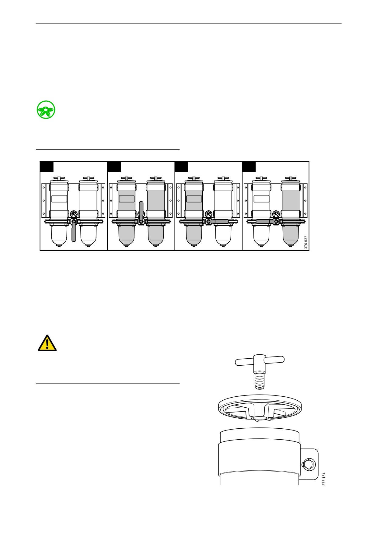
Draining the commutative wa-
ter separating prefilter (op-
tion)
During operation, the arrow on the rotary control
should point towards the filter being used.
Environment
Use a suitable container. The fuel collected must
be disposed of as specified in national and inter-
national laws and regulations.
1
2
3
4
1. Closed; neither filter is active.
2. Both filters are active.
3. Left-hand filter is active.
4. Right-hand filter is active.
1. Switch off the filter that needs renewing. The
arrow on the rotary control points towards
the filter in operation.
WARNING!
Be careful that the valve does not pass the closed
position when the engine is in operation. A
closed position can result in the engine stopping.
2. Remove the cover from the filter housing.
63