Scania DI13 PDE. Marine engine en-GB 2 805 601. Operator’s manual - part 5
Fuel system
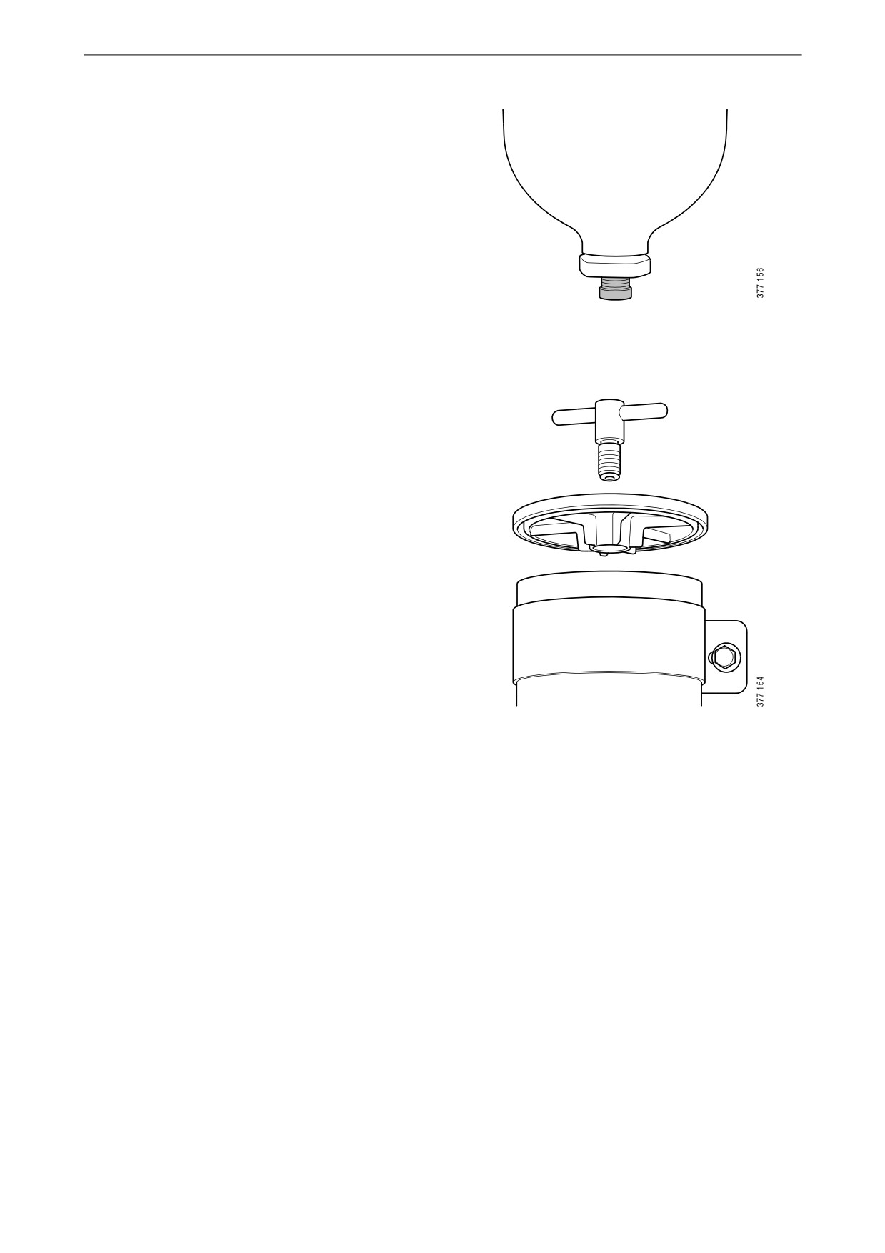
3. Undo the drain plug.
4. Tighten the drain plug when all the water has
emptied.
5. Fill the filter housing with clean fuel.
6. Fit the cover. Tighten the cover screw by
hand.
64
Fuel system
Renewing the commutative
water separating prefilter (op-
tion)
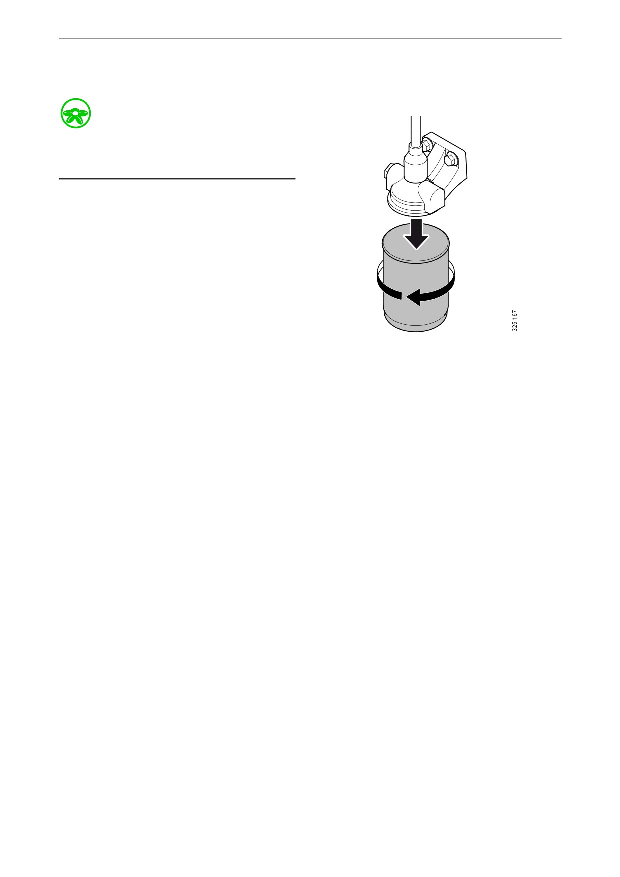
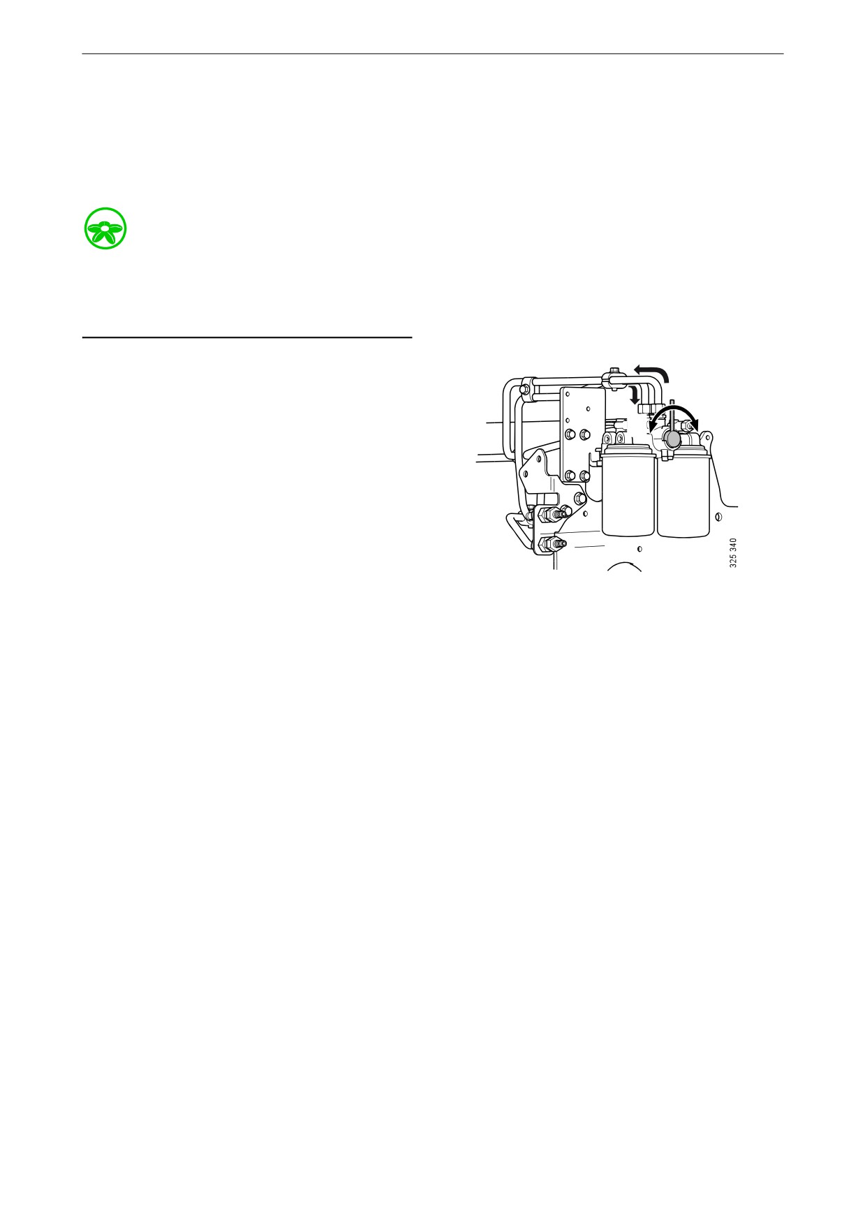
During operation, the arrow on the rotary control
should point towards the filter being used.
Environment
Use a suitable container. The fuel collected must
be disposed of as specified in national and inter-
national laws and regulations.
1. Switch off the filter that needs renewing.
During renewal, the arrow on the rotary con-
trol points towards the filter in operation.
WARNING!
Be careful that the valve does not pass the closed
position when the engine is in operation. A
closed position can result in the engine stopping.
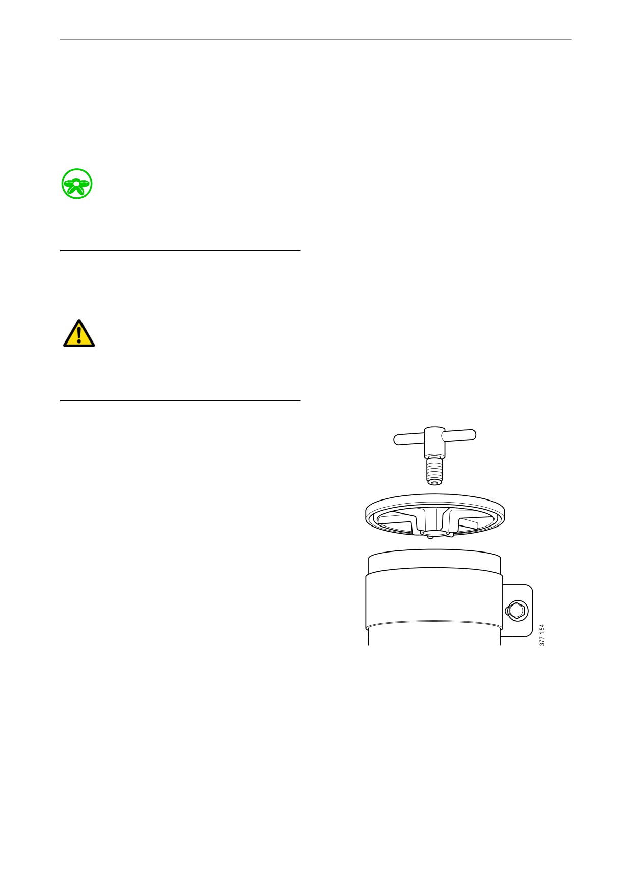
2. Clean the filter housing externally with a
cloth.
3. Remove the cover from the filter housing.
65
Fuel system
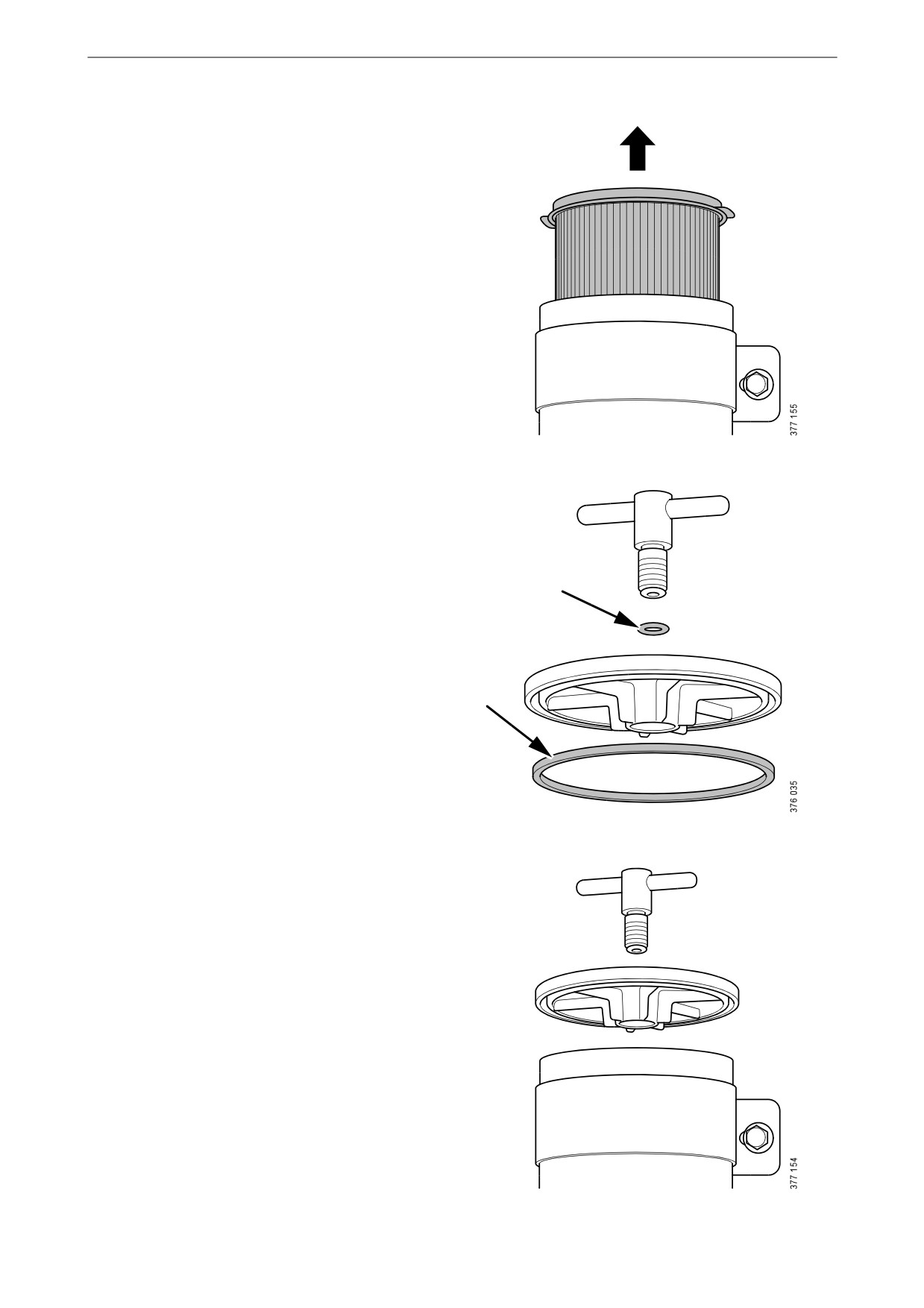
4. Remove the filter and fit the new filter.
5. Renew the O-rings in the cover.
6. Lubricate the O-rings with engine oil.
7. Fill the filter housing with clean fuel.
8. Fit the cover. Tighten the cover screw by
hand.
66
Fuel system
Renewing the fuel filter
Environment
Use a suitable container. The fuel collected must
be disposed of as specified in national and inter-
national laws and regulations.
1. Clean the exterior of the filter with a damp
cloth.
2. Unscrew the filter.
3. Apply oil to the gasket on the new filter.
4. Screw the filter into place by hand until it
makes contact.
5. Screw a further half turn by hand.
6. Bleed the fuel system according to the in-
structions in the Bleeding the fuel system
section.
67
Fuel system
Renewing and bleeding com-
mutative fuel filters (option)
During operation, the rotary control should point
90° towards the filter being used.
Environment
Since the engine may be running during filter re-
newal, fuel spillages may occur. Use a suitable
container. Any fuel collected must be disposed
of as specified in national and international law.
1. Turn the rotary control 90° to the right so that
it points towards filter B. The fuel then flows
through the filter.
B
A
2. Connect a clear plastic hose to the bleed nip-
ple positioned above filter A. Start by wiping
off the bleed nipple. Place the other end in a
A
B
container with a capacity of at least 3 litres
(1 US gallon).
3. Open the bleed nipple on side A. The re-
maining pressure is released.
4. Clean the exterior of the filter with a cloth.
5. Unscrew the filter.
6. Apply oil to the gasket on the new filter.
7. Screw the fuel filter into place by hand until
it makes contact. Turn screw a further half
turn by hand.
8. Turn the rotary control 90° to the left so that
the rotary control points straight up. Both fil-
ters now run simultaneously.
9. When fuel without air bubbles comes out:
Close the bleed nipple. Because the engine is
running, a lot of fuel will come through the
hose.
10. Turn the rotary control 90° to the left so that
the rotary control points towards filter A. Fil-
ter B can now be renewed in the same way as
filter A.
68
Fuel system
Bleeding the fuel system
Bleeding the fuel system using a suc-
tion tool
Tools
Designation
Illustration
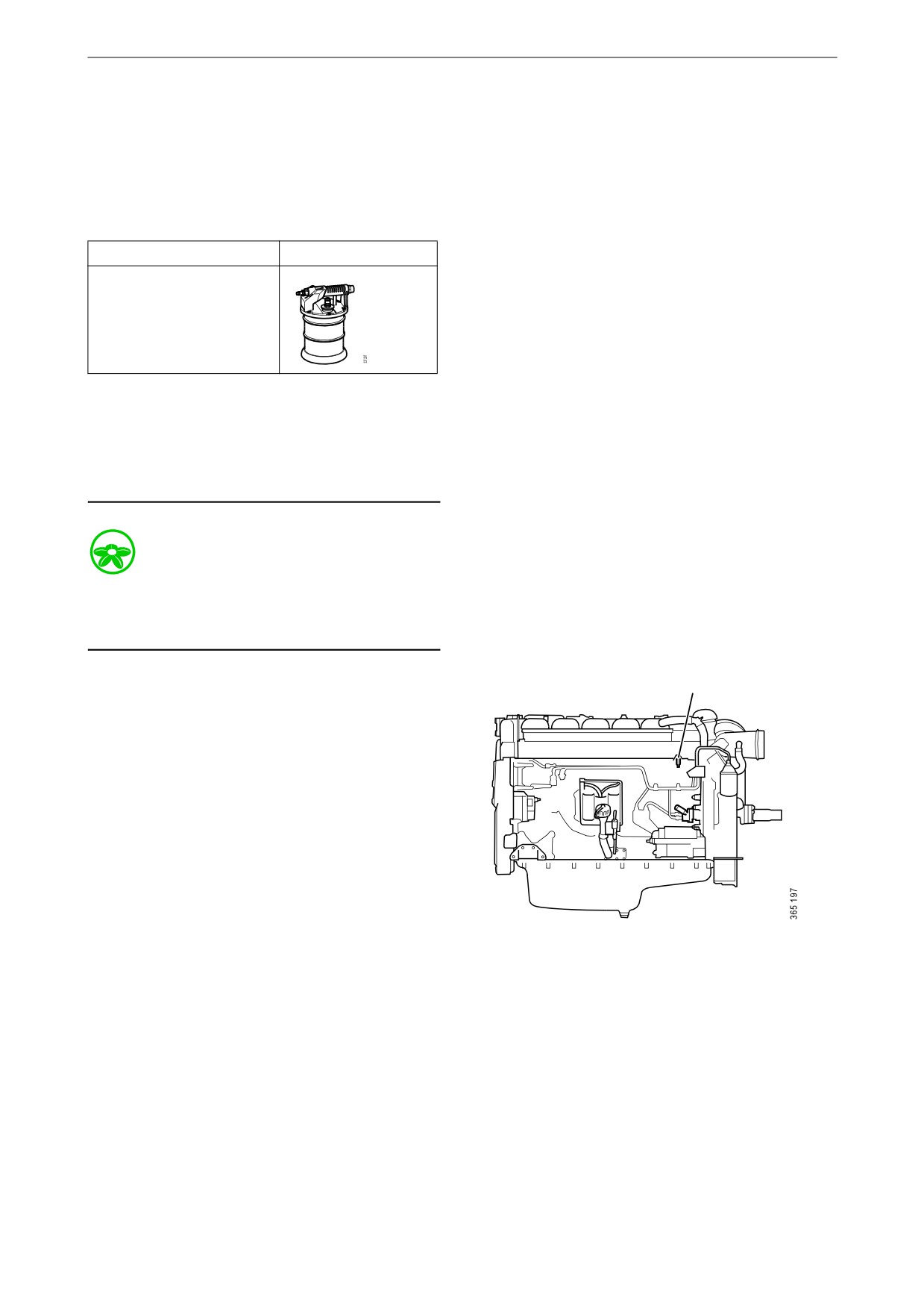
Suction tool for fuel sys-
tem
Note:
Scania recommends bleeding the fuel system us-
ing suction tools rather than with a hand pump.
This is a quicker and simpler method, which en-
sures a complete bleeding.
Environment
Use a suitable container. The fuel collected must
be disposed of as specified in national and inter-
national laws and regulations.
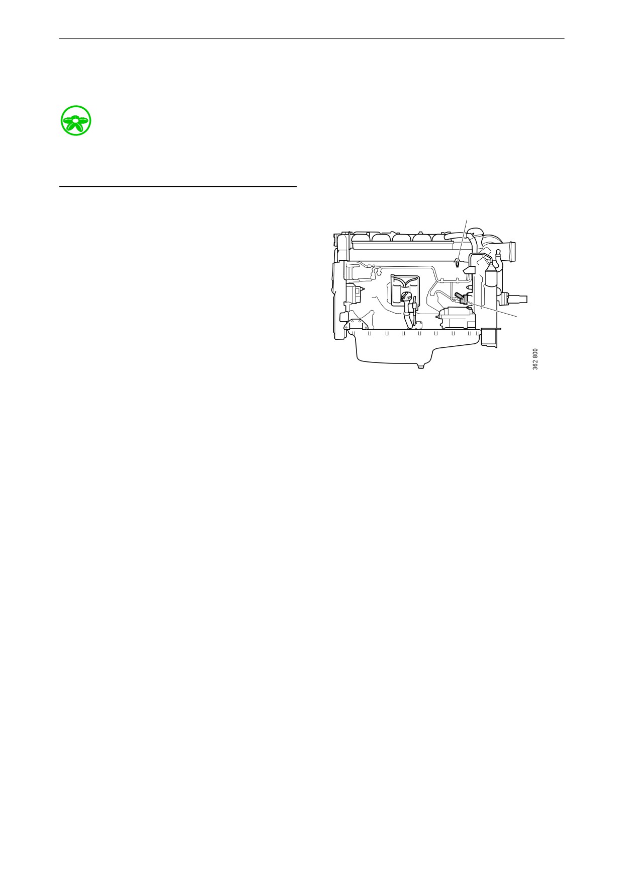
1. Attach a clear plastic hose to the bleed nipple
on the fuel manifold. Start by wiping off the
bleed nipple. Place the end of the plastic hose
in a container that holds at least 3 litres (1 US
gallon).
2. Connect the suction tool.
3. Connect compressed air to the suction tool.
Turn the rotary control to create a vacuum.
4. Open the bleed nipple.
5. Hold the suction tool straight and draw out
the fuel. Once the fuel coming out of the
plastic hose is free of air bubbles, then bleed-
ing is complete.
Fuel manifold bleed nipple.
6. Close the bleed nipple. Remove the plastic
hose and suction tool.
7. Start the engine and check that no leakage
occurs.
69
Fuel system
Bleeding the fuel system using a
hand pump
Environment
Use a suitable container. The fuel collected must
be disposed of as specified in national and inter-
national laws and regulations.
1. Attach a transparent plastic hose to the bleed
1
nipple on the fuel manifold (1). Start by wip-
ing off the bleed nipple. Place the end of the
plastic hose in a container that holds at least
3 litres (1 US gallon).
2. Open the bleed nipple and pump with the
hand pump (2) until fuel comes out of the
hose. If the fuel system is empty, it is neces-
sary to pump approximately 200 strokes in
2
order to draw up the fuel. Depending on the
installation, a significantly greater number of
pump strokes may be required before fuel
comes out.
3. Pump until fuel without air bubbles comes
out, approximately 20 strokes.
4. Close the bleed nipple and remove the plastic
hose.
5. Pump approximately 20 strokes with the
hand pump until the overflow valve opens. A
hissing sound should be heard.
6. Start the engine. The engine should be easy
to start.
7. If the fuel filter has been renewed, check that
no fuel is leaking from the filter. If there is
leakage, tighten the filter more.
70
Miscellaneous
Miscellaneous
2
5
4
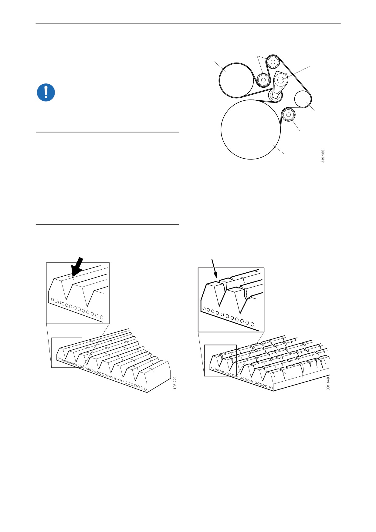
Checking the drive belt
IMPORTANT!
Before starting, make a note of how the drive belt
is fitted. Refit the drive belt with the same direc-
3
tion of rotation as it had before removal.
2
1. Check the drive belt for cracks. Renew the
drive belt if deep cracks have formed.
1
Note:
Example of a drive belt.
Small and shallow cracks are normal and form
1. Crankshaft.
after only a few hours of operation. They do not
2. Idler roller.
mean that the drive belt needs to be renewed. If
there are many deep cracks, or if parts of the
3. Alternator.
drive belt have started to come off, the drive belt
4. Belt tensioner.
must then be renewed.
5. Coolant pump.
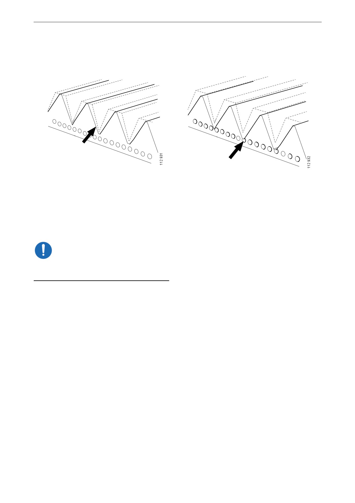
Example of a minor crack in the drive belt. The drive
The drive belt has deep cracks and must be renewed.
belt can be refitted.
71
Miscellaneous
2. Check drive belt wear. Renew the drive belt
if it is too worn.
The drive belt is starting to become worn, but can be
The belt is worn down to the cord. The drive belt
refitted.
must be renewed.
Checking for leaks
IMPORTANT!
If serious leakage occurs, contact your nearest
workshop.
1. Start the engine.
2. Check for oil, coolant, fuel, air or exhaust
leaks.
3. Tighten or renew leaking connections.
Check the overflow holes which show
whether the O-rings between the cylinder
liners and crankcase are leaking.
4. Check whether the drain hole on the coolant
pump is blocked. If there is a leak, renew the
seal in the pump or the complete coolant
pump.
72
Miscellaneous
Checking and adjusting the
valve clearance and unit in-
jectors
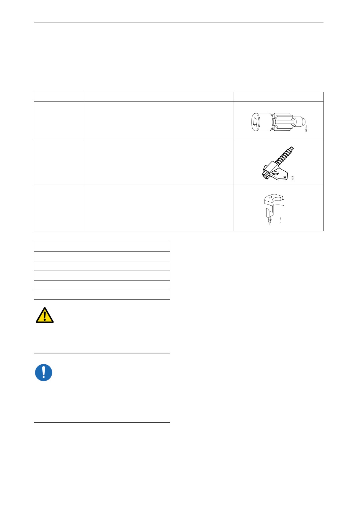
Special tools
Number
Designation
Illustration
99 309
Turning tool for rotating the flywheel from below
2 402 509
Turning tool for rotating the flywheel from above
99 442
Setting tool
Other tools
Torque wrench, 0-50 Nm
Waterproof felt-tip pen
0.45 and 0.70 mm feeler gauges
Flash light
Mirror
WARNING!
Block the starting device or remove a battery ca-
ble. If the engine starts unexpectedly, there is a
serious risk of injury.
IMPORTANT!
The engine must be cold when the work is car-
ried out.
Remember to remove the turning tool from the
flywheel after adjustment.
Note:
Carry out the working without pausing, so that
no step is overlooked.
73

Miscellaneous
Carry out a check and adjustment of the valve
clearances and the unit injectors one more time
after the first 500 hours of operation. After this,
adjustment according to the regular interval
takes place, which is every 2,000 operational
hours.
On the flywheel is engraved the reference infor-
mation UP TDC, DOWN TDC and the angle in-
dications listed in the table below. Depending on
the engine installation, this information is visible
in one of the windows, either furthest up or fur-
thest down on the flywheel. See illustration.
Upper and lower window to read the engraving on
the flywheel.
1
2
Workflow table
3
Adjust valves and injectors according to the table
4
below. Follow the respective column depending
5
on whether you are reading the engraving on the
flywheel in the lower or the upper window. Start
6
adjustment at the top of the table.
Order of cylinders.
Reading in the low-
Valve transition on
Adjust valves on
Adjust injector on
Reading in the up-
er window
cylinder
cylinder
cylinder
per window
DOWN TDC
1
6
2
UP TDC
120/480
5
2
4
300/660
240/600
3
4
1
60/420
DOWN TDC
6
1
5
UP TDC
120/480
2
5
3
300/660
240/600
4
3
6
60/420
74
Miscellaneous
Checking and adjusting the valve
clearance
Valve clearance, specifications
Intake valve
0.45 mm (0.018 in)
Exhaust valve
0.70 mm (0.028 in)
Tightening torques
Lock nut for valves
35 Nm (26 lb/ft)
1. Clean the rocker covers and the area around
them.
2. Remove the rocker covers.
3. Use the turning tool appropriate to the instal-
lation of the engine. Tool 99 309 is used to
rotate the flywheel from the underside of the
engine and tool 2 402 509 is used from the
top side.
4. Start adjusting one cylinder according to the
table. Rotate the flywheel until the correct
engraving can be read on the flywheel. It
may be necessary to rotate it more than 1 rev-
olution.
Rotate the flywheel in the rotational direc-
tion of the engine, which is clockwise
viewed from the front of the engine and anti-
clockwise viewed from the back of the en-
gine.
During a valve transition, the exhaust valve
(the long arm) is closing at the same time as
the intake valve is opening.
The UP TDC engraving on the flywheel is
now visible in the window furthest up on the
flywheel. The DOWN TDC engraving is vis-
ible in the lower window.
5. Read Workflow table on the previous page to
3
see which valve to adjust.
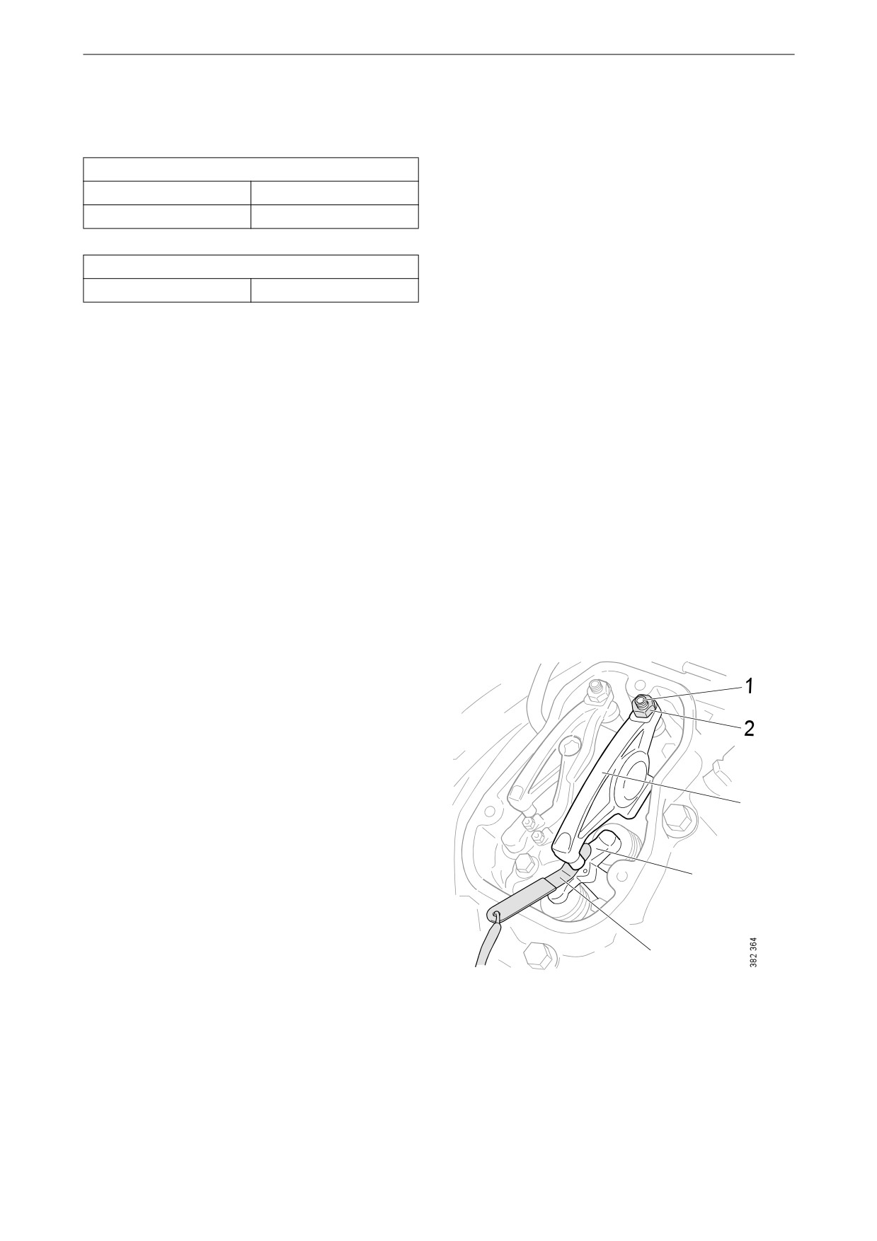
6. Stick the feeler gauge under the pressure pad
of the rocker arm and check the valve clear-
4
ance.
7. If necessary, adjust the valve clearance by
a) loosening the lock nut on the end of the
rocker arm
5
b) adjusting the valve clearance with the ad-
justing screw
1.
Adjusting screw.
c) tightening the lock nut.
2.
Lock nut.
8. Mark the rocker arm with the felt-tip pen and
3.
Rocker arm.
adjust the unit injector according to the next
4.
Valve bridge.
section. Then continue on to the next cylin-
5.
Feeler gauge.
der according to the table.
75
Miscellaneous
Checking and adjusting the unit in-
jectors
Tightening torques
Lock nut for unit injec-
39 Nm (29 lb/ft)
tors
1. See the Workflow table for details of the in-
jectors to be adjusted.
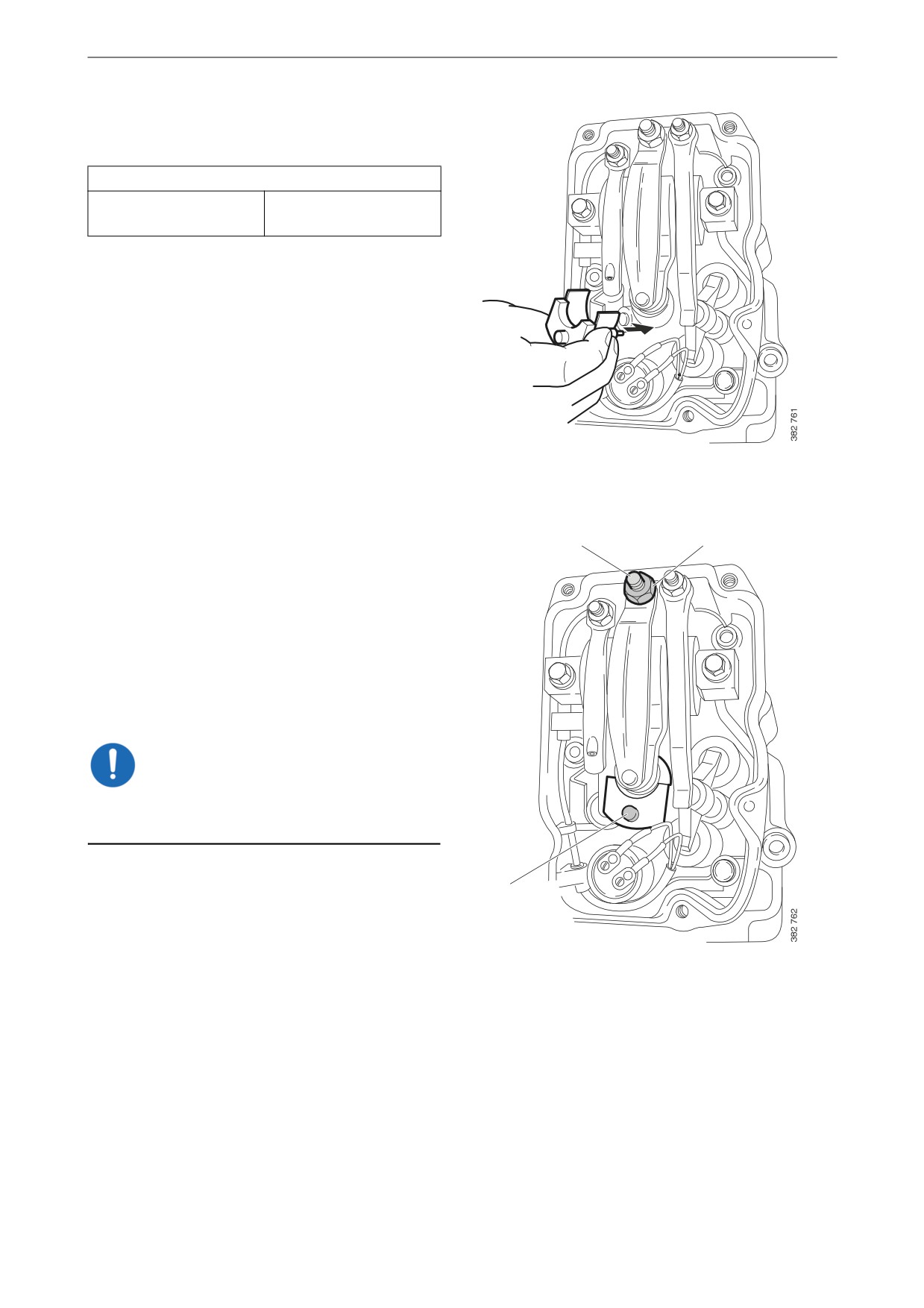
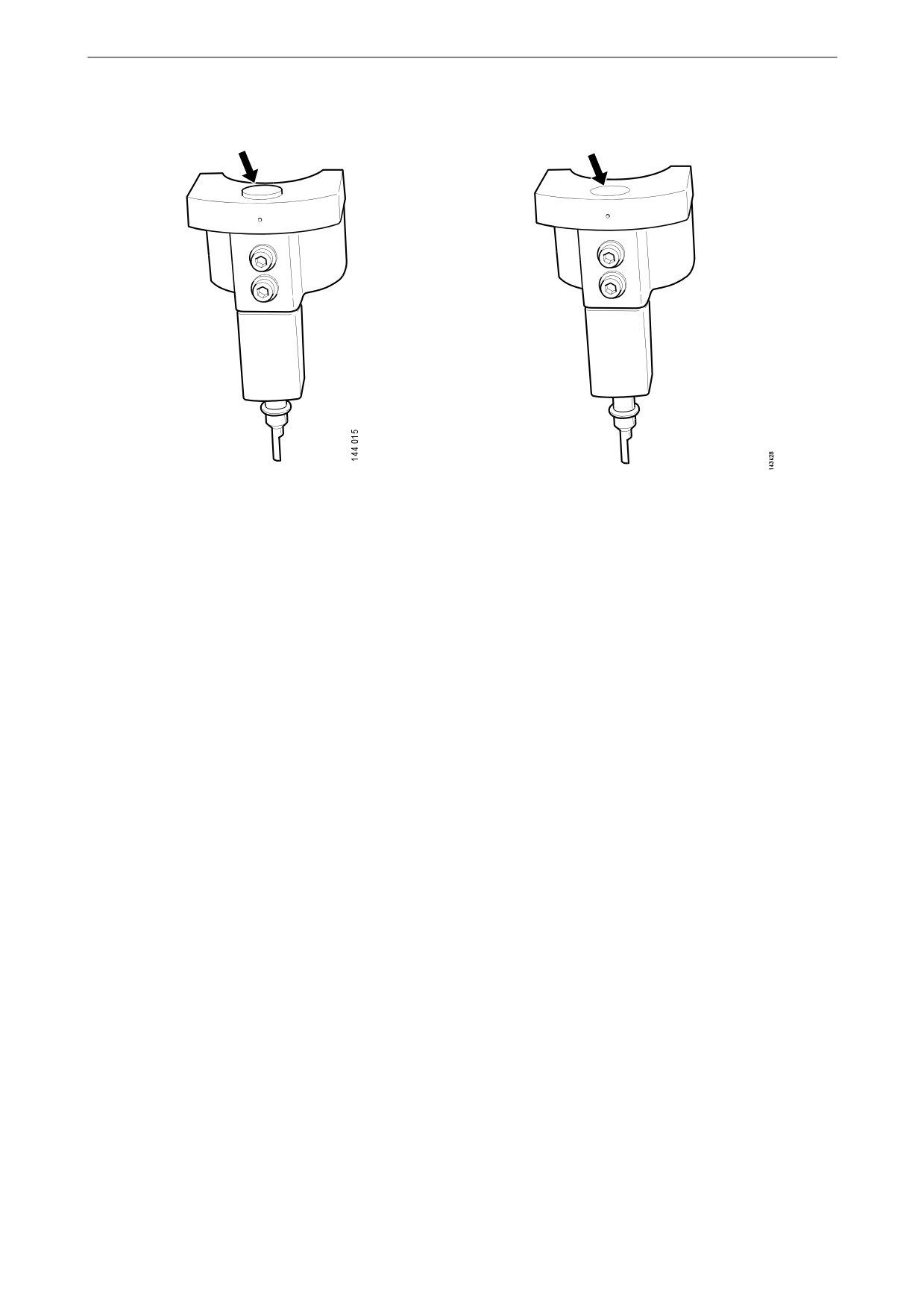
2. Fit the setting tool with the metal plate
around the unit injector.
The unit injector is correctly set when the
3
2
small piston (1) is level with the flat upper
surface of the tool. Use a finger to check.
You can feel very small differences. See also
the illustrations on the next page.
3. If necessary, adjust the unit injector by
a) loosening the lock nut (2)
b) adjusting the unit injector using the adjust-
ing screw (3)
c) tightening the lock nut.
IMPORTANT!
Remove the setting tool when the adjustment is
done.
4. Mark the injector with the felt-tip pen and
1
continue adjustment according to the table.
76
Miscellaneous
The setting tool piston is above or below the flat
The setting tool piston is level with the flat upper
upper surface of the tool. Adjust the unit injector. surface of the tool. The unit injector is correctly
adjusted.
77
Miscellaneous
Renewing the reductant fil-
ters
Note:
3
There is always one reductant pump with a filter
in the reductant tank (buffer tank). However,
there may be an additional reductant pump with
4
a filter between the main reductant tank and the
buffer tank.
5
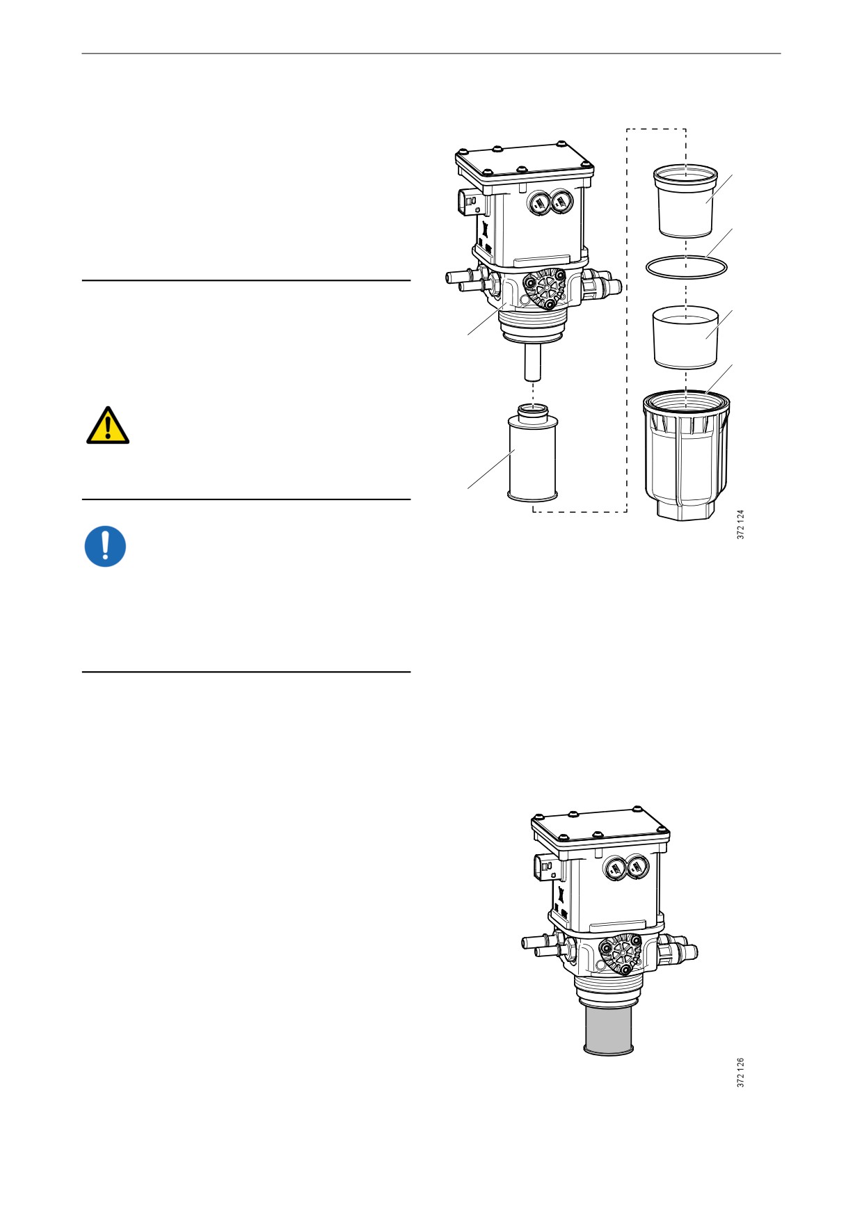
1. Wipe clean around the filter housing to pre-
vent impurities from penetrating it.
1
2. Remove the filter housing. Use a 46 mm
6
socket.
WARNING!
There may be a lot of reductant in the filter hous-
ing and it may spill out. Wear protective gloves.
2
IMPORTANT!
1.
Reductant pump.
Always rinse away reductant spillage on connec-
2.
Filter.
tions and other parts with lukewarm water to pre-
3.
Sealing diaphragm.
vent corrosion. If reductant seeps into electrical
4.
O-ring.
connections or electrical cables, these must be
5.
Antifreeze.
renewed.
6.
Filter housing.
3. Remove the sealing diaphragm.
4. Remove the old reductant filter and fit a new
one.
78
Miscellaneous
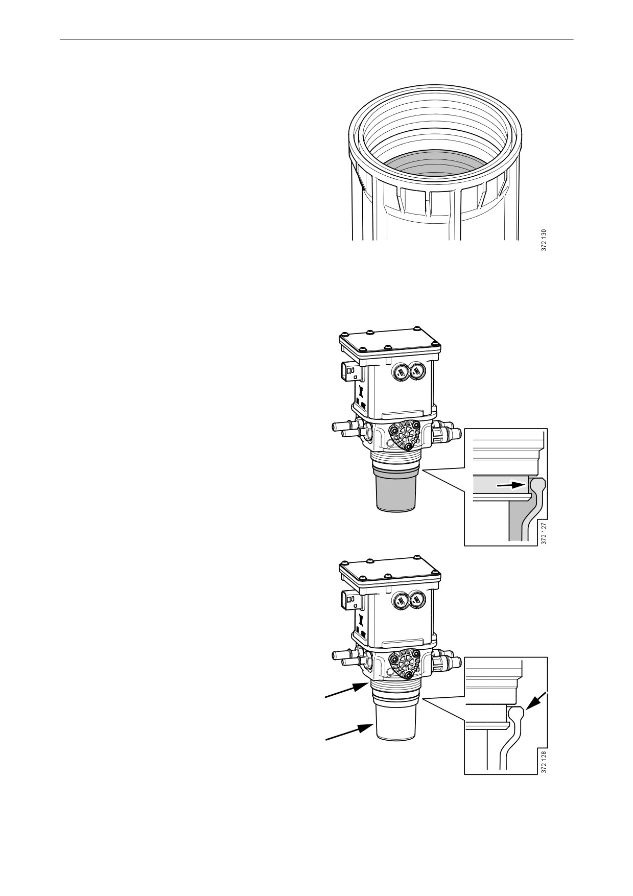
5. If the anti-freeze protection in the filter hous-
ing comes loose, wipe both the anti-freeze
protection and filter housing thoroughly so
that they are completely dry before they are
assembled again.
6. Wipe the sealing diaphragm and fit it over
the filter.
Ensure that the edge of the diaphragm is sit-
ting in the groove.
7. Lubricate the sealing diaphragm and threads
with the accompanying spray.
79