Scania DI13 PDE. Marine engine en-GB 2 805 601. Operator’s manual - part 2
Component identification
Component identification
Engine
11
12
13
8 14
15 16
10
17
1
1
2
3
4
9
18
8
19
22
5
6
21
20
7
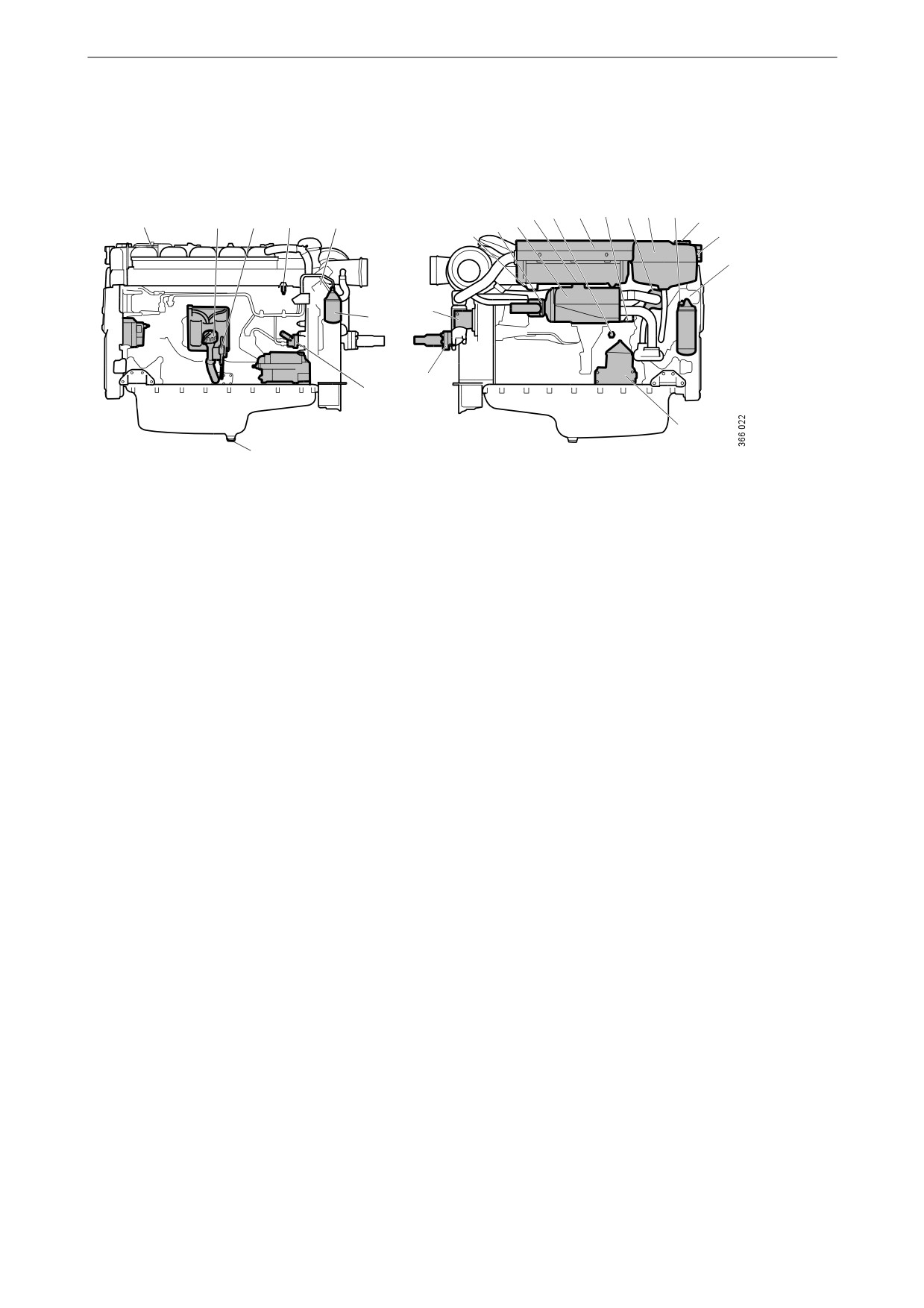
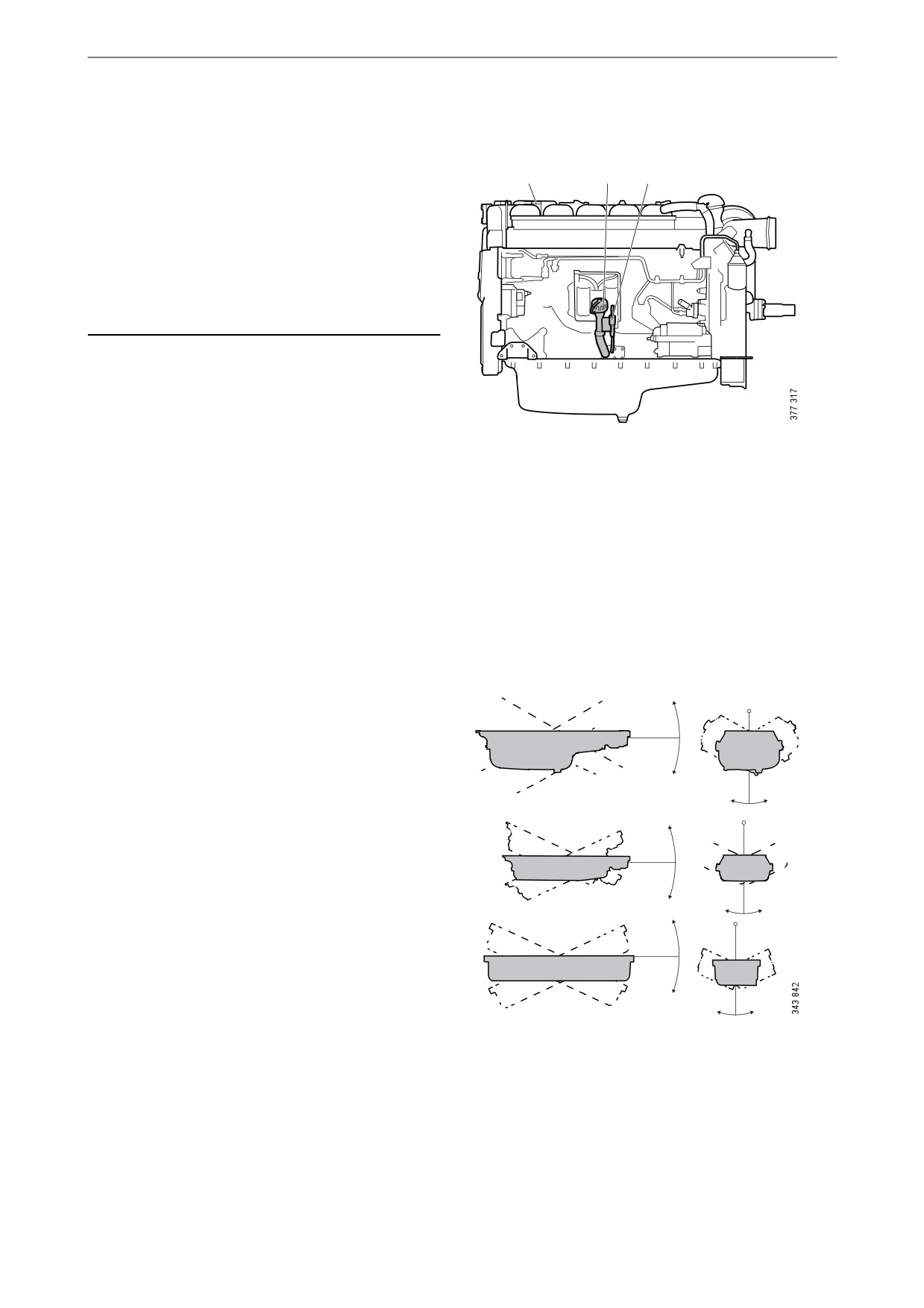
The illustration shows a normal version of a DI13 engine with heat exchanger. The engine ordered may have
different equipment.
1. Oil filler.
2. Oil dipstick.
3. Fuel manifold bleed nipple.
4. Engine data plate.
5. Fuel filter.
6. Hand pump for fuel.
7. Oil plug.
8. Sacrificial anodes (2).
9. Sea water outlet.
10. Heat exchanger.
11. Holes for draining condensation in charge air cooler.
12. Nipple for draining and filling coolant.
13. Charge air cooler.
14. Thermostat.
15. Expansion tank.
16. Oil filter.
17. Filling coolant.
18. Level glass for checking coolant level.
19. Engine number, stamped into the cylinder block.
20. Centrifugal oil cleaner.
21. Sea water intake.
22. Sea water pump.
16

Component identification
SCR system
For engines equipped with SCR systems, the il-
lustration shows an overview of the component
parts of the SCR system.
1
2
4
3
2
6
3
13
5
12
6
14
11
8
9
7
10
1. Reductant pump (option).
2. Reductant pressure pipe.
3. Reductant return pipe.
4. Reductant tank (buffer tank).
5. Engine control unit.
6. NOx sensor with control unit.
7. Coolant pipe.
8. Exhaust routing valve.
9. Handle to bypass the SCR system.
10. Bypass pipe.
11. Evaporator.
12. Reductant doser.
13. Exhaust gas temperature sensor.
14. SCR catalytic converter.
17

Starting and running
Starting and running
Checks before first start
Before the engine is started for the first time, car-
ry out the maintenance items listed under First
start in the maintenance schedule. Check the fol-
lowing (also see Maintenance interval):
• Oil level.
2
• Coolant.
1
• Fuel level.
3
• Fluid level in batteries.
• State of battery charge.
4
• Condition of the drive belt.
Reductant tank
The illustration shows the component parts of
the reductant tank (buffer tank). You can access
the reductant pump in the tank by opening the in-
spection hatch (4) on the right-hand side of the
tank.
Reductant volume:
• Total volume: 30 litres (7.9 US gallons).
• Filling volume: 16 litres (4.2 US gallons).
6
5
Reductant tank.
1. Reductant pick-up unit.
2. Reductant pump.
3. EEC3 control unit.
4. Inspection hatch.
5. Drain plug.
6. Reductant tank.
18
Starting and running
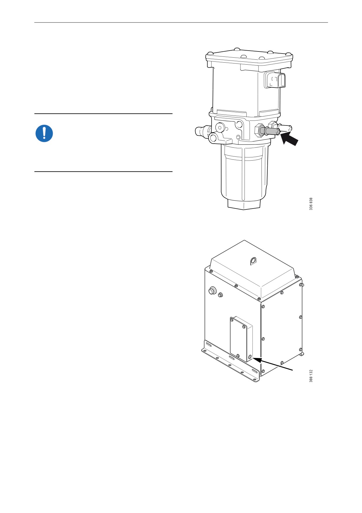
Reductant pump
When the reductant pump is new, the check
valves may need to be slackened.
Note:
There may be two reductant pumps: one located
in the reductant tank and one located between the
main tank for reductant and the buffer tank.
IMPORTANT!
Blow the reductant pump suction nipple with
compressed air (approx. 6 bar) for at least 3 sec-
onds before starting the engine for the first time.
Reductant pump suction nipple.
Reset button on the reductant tank
The reductant tank has a reset button that can be
used, for example, when the tank is topped up for
the first time.
When the Scania EEC3 control unit checks fill-
ing, the following applies:
• If you keep the button depressed for 5 sec-
onds, the reductant pump operates for 30 min-
utes. This function can be used, for example,
when the tank is topped up for the first time
or after cleaning.
• If the reductant pump is operating and you
briefly press the button, the pump stops and a
fault code is generated.
The reductant pump can be started again by
pressing the button, thus also making the
fault code passive.
Reset button.
• If the level does not increase even though the
reductant pump is running, the pump is
switched off and a fault code is generated. If
you briefly press the button, the pump re-
starts.
19
Starting and running
Checks before running
Starting at low temperatures
Take the local environmental requirements into
Carry out daily maintenance as described in the
account. Use a fuel heater and engine heater to
maintenance schedule prior to operation. See
avoid starting problems and white smoke.
Maintenance interval.
Scania recommends that an engine heater should
be used if the engine will be used at temperatures
below -10°C (14°F).
Starting the engine
A low engine speed and a moderate load on a
cold engine limits white smoke, gives better
combustion and warms up the engine more
WARNING!
quickly than warming it up with no load.
Never use starter gas or similar agents to help
Avoid running it longer than necessary at idling
start the engine. This can cause an explosion in
speed.
the intake manifold and possible injury.
Only start the engine in a well ventilated area.
When the engine is run in an enclosed space,
Running
there must be effective devices to extract exhaust
Check instruments and warning lamps at regular
gases and crankcase gases.
intervals.
Engine speed range
IMPORTANT!
The engine operating speed range is between low
idling and the nominal engine speed. The nomi-
The starter motor must only be cranked twice for
nal engine speed is indicated on the engine data
30 seconds at a time. After that, it must rest for at
plate. Low idling can be set between 500 and
least 5 minutes before the next attempt to start it.
1,050 rpm.
For environmental reasons the Scania engine has
been developed to be started with a low fuel feed.
Using unnecessarily large amounts of fuel when
starting the engine always results in emissions of
unburnt fuel.
1. Open the fuel cock if fitted.
2. Disengage the engine.
3. If the engine has a battery master switch:
Switch on the power by means of the battery
master switch.
4. Start the engine.
If the fuel tank has been run dry or if the engine
has not been used for a long time, bleed the fuel
system. See the section Bleeding the fuel system.
20
Starting and running
Limp home mode
Coolant temperature
If there is a fault in the normal throttle opening or
if CAN communication is interrupted, the fol-
IMPORTANT!
lowing emergency operation option is provided:
An excessive coolant temperature can cause en-
A CAN fault or throttle opening fault in an all-
gine damage.
speed engine (both signal and idling switch):
• The throttle opening value is 0% and the en-
Normal coolant temperature during operation is
gine is running at normal idling speed.
90 to 95°C/194 to 203°F for engines with a heat
• The throttle opening value is 0% and the en-
exchanger and 83 to 88°C/181 to 190°F for en-
gine is running at raised idling speed (750
gines with keel cooling.
rpm) if this function is activated.
Alarm levels are set in the engine control unit.
CAN fault:
The default setting for the lowest and highest
limit values for high coolant temperature are
• The engine is switched off if the shutdown
95°C/203°F and 105°C/221°F respectively.
function is activated.
The high coolant temperature alarm has the fol-
Driving at high altitude
lowing functions:
When driving at high altitudes engine power is
• Alarm only.
reduced automatically due to the lower oxygen
• Alarm and torque reduction at the lowest lim-
content in the air. It is then not possible to run the
it value.
engine at maximum power.
• Alarm at the lowest limit value and engine
• ICFN and PRP engines may be used at an al-
shutdown at the highest limit value.
titude of up to 2,000 metres.
• Alarm, torque reduction at the lowest limit
• IFN, Patrol Craft Long and Patrol Craft Short
value and engine shutdown at the highest lim-
engines must not be used at an altitude of
it value.
more than 1,000 metres.
• Alarm at the lowest limit value and engine
• Contact Scania if the operating conditions de-
shutdown at the highest limit value with the
viate from these.
possibility of engine shutdown override con-
trol.
• Alarm, torque reduction at the lowest limit
value and engine shutdown at the highest lim-
it value, with the possibility of engine shut-
down override control.
If run for extended periods under an extremely
light load, the engine may have difficulty in
maintaining the coolant temperature. At an in-
creased load the coolant temperature rises to the
normal value.
21
Starting and running
Oil pressure
Alarm levels, engines with SCR system
Normal oil pressure during operation is 3-6 bar
If the engine is equipped with the SCR system,
(43.5-87 psi). The lowest permitted oil pressure
the engine management system activates an
when idling is 0.7 bar (10.2 psi).
alarm at the levels below. The values refer to
overpressure, not absolute pressure. The alarm is
The incorrect oil pressure alarm has the follow-
activated after 10 seconds.
ing functions:
• At an engine speed below 600 rpm and an oil
• Alarm only.
pressure below 0.7 bar (10.2 psi).
• Alarm and torque reduction by 30%.
• At 1,200 rpm and with oil pressure below
• Alarm and engine shutdown.
2.2 bar (32 psi).
• Alarm and engine shutdown override control.
• At 2,100 rpm and with oil pressure below
2.8 bar (40.6 psi).
Note:
High oil pressure (above 6 bar/87 psi) is normal
if the engine is cold when started.
Charging indicator lamp
If the lamp comes on during operation: Check
and adjust the alternator drive belt according to
the instructions in the section Checking the drive
Alarm levels, engines without SCR sys-
belt.
tem
If the charging indicator lamp is still on, this
If the engine does not have the SCR system, the
could be due to an alternator fault or a fault in the
engine management system activates an alarm at
electrical system.
the levels below. The values refer to overpres-
sure, not absolute pressure. The alarm is activat-
ed after 3 seconds.
Belt transmission
• At an engine speed below 1,000 rpm and an
oil pressure below 0.7 bar (10.2 psi).
When the belt transmission is new, it may make
a squeaking noise when running. This noise is
• At an engine speed above 1,000 rpm and an
normal and disappears after 50-100 hours of op-
oil pressure below 2.5 bar (36.3 psi).
eration. The noise does not affect the service life
of the belt transmission.
22
Starting and running
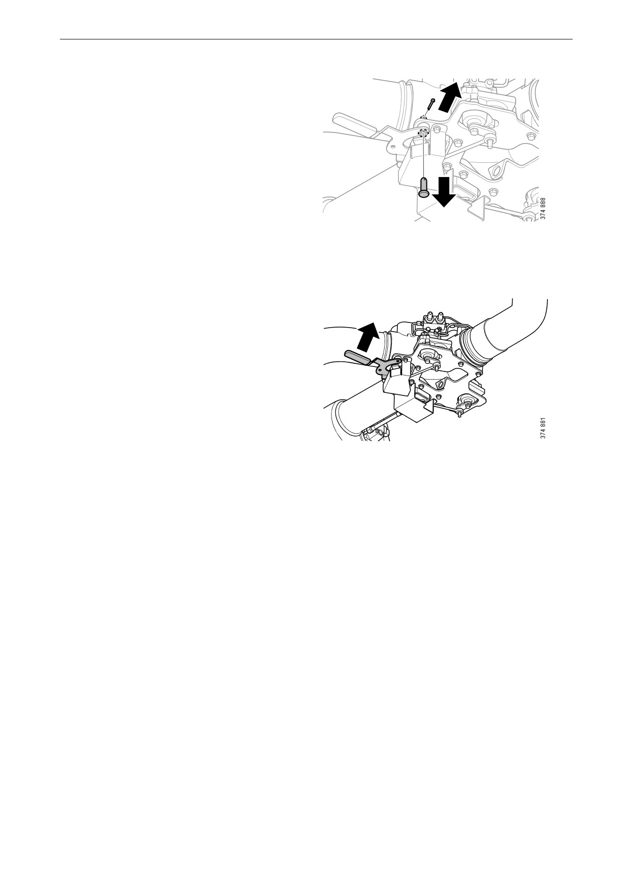
Bypass of the SCR system
If the SCR system has been activated and needs
1
to be bypassed in an emergency, this can be done
manually using the handle on the exhaust routing
valve.
Proceed as follows:
1. Remove the pin.
2. Remove the bolt.
2
3. Pull the handle to the Open position. See il-
lustration.
4. Lock the handle in the open position using
the pin and the bolt.
23
Starting and running
Engine shutdown
Checks after running
IMPORTANT!
WARNING!
There is risk of the oil boiling and of damage to
Secure the starting device or disconnect a battery
the turbocharger if the engine is switched off
cable before working on the engine. If the engine
without cooling. The power must not be
starts unexpectedly, there is a serious risk of in-
switched off before the engine has stopped.
jury.
If the engine is equipped with a battery master
There is always a risk of sustaining burns when
switch and an SCR system, the SCR system must
an engine is hot. Particularly hot parts are engine
run for a while after the engine has been switched
manifolds, turbochargers, oil sumps, as well as
off to allow it to cool down. During this period
hot coolant and oil in pipes and hoses.
the power must not be cut using the battery mas-
ter switch.
IMPORTANT!
Note:
Check the coolant level following the first start.
The battery voltage must remain on for a few
Top up with coolant as necessary.
seconds after the 15 voltage is switched off so
that the control units can store the values and
switch to standby mode.
1. Check that the power supply has been cut.
10 prohibited engine shutdowns in a row will
2. Top up the fuel tank. Make sure that the filler
cause a torque reduction (70% of fuel quantity).
cap and the area round the filler opening are
Reset the engine by switching it off correctly
clean to avoid contamination of the fuel.
once.
3. If the engine is equipped with an SCR sys-
tem: Top up the reductant tank. Make sure
that the filler cap and the area round the filler
1. Run the engine without a load for a few min-
opening are clean to avoid contamination of
utes if it has been run continuously with a
the reductant.
heavy load.
4. If there is a risk of freezing, the cooling sys-
2. Switch off the engine.
tem must contain enough glycol. See the sec-
tion Risk of freezing.
5. If the temperature is below 0°C (32°F): Pre-
pare for the next start by connecting the en-
gine heater (if fitted).
24

Maintenance
Maintenance
IMPORTANT!
The maintenance programme covers a number of
points that are divided into the following sec-
On delivery a Scania engine is optimised for its
tions:
application. However, regular maintenance is
necessary to
• Lubrication system.
•
prevent unplanned stops
• Air cleaner.
•
extend the service life of the engine
• Cooling system.
•
maximise the long-term emission perfor-
• Fuel system.
mance of the engine
• Miscellaneous.
•
give the best possible operating economy.
WARNING!
Secure the starting device or disconnect a battery
cable before working on the engine. If the engine
starts unexpectedly, there is a serious risk of in-
jury.
There is always a risk of sustaining burns when
an engine is hot. Particularly hot parts are engine
manifolds, turbochargers, oil sumps, as well as
hot coolant and oil in pipes and hoses.
The maintenance programme includes the fol-
lowing:
• R maintenance: One event when taken into
service.
• S maintenance: Minimum basic maintenance.
• M maintenance: More extensive mainte-
nance.
• L maintenance: Includes nearly all mainte-
nance items in the form.
• XL maintenance: Includes all maintenance
items in the form.
During a period, the sequence is S-M-S-L-S-M-
S-L-S-M-S-XL.
XL
L
L
M
M
M
S
S
S
S
S
S
500
1000
1500
2000
2500
3000
3500
4000
4500
5000
5500
6000
25

Maintenance
Maintenance interval
Daily
First time at
Interval (hours)
Minimum
first start
500
500
1,000
2,000
6,000
annu-
every
ally
5
R
S
M
L
XL
years
Lubrication system
Checking the oil level
X
X
Changing the oil
X
X
X
X
X
X
Cleaning the centrifugal oil
X
X
X
X
X
X
cleaner
Renewing the oil filter
X
X
X
X
X
X
Air cleaner
Reading the vacuum indicator
X
X
X
X
X
X
Renewing the filter element
X
X
X
Renewing the safety cartridge
X
X
X
Renewing an air filter with a
X
X
X
non-renewable element
Cooling system
Checking the coolant level
X
X
X
X
X
X
X
Checking coolant antifreeze and
X
X
X
X
corrosion protection
Checking sacrificial anodes
X
X
X
X
X
X
Checking the sea water pump
X
X
X
X
X
X
impeller
Changing the coolant and clean-
X
X
ing the cooling system
Fuel system
Checking the fuel level
X
X
Draining the water separating
X
X
X
X
X
X
prefilter
Renewing the fuel filters
X
X
X
X
Miscellaneous
Checking the drive belt
X
X
X
X
X
Checking for leaks
X
X
X
X
X
X
Checking and adjusting the valve
X
X
X
clearance and unit injectors
Renewing the reductant filters
X
X
X
X
X
X
26

Lubrication system
For operation at extremely low outdoor tempera-
Lubrication system
tures: Consult your nearest Scania representative
on how to avoid starting difficulties.
Oil grade
Scania LDF stands for the Scania Long Drain
Viscosity
Outdoor temperature in °C
Field test standard. Scania LDF oils have been
class
carefully selected after extensive testing. The ap-
SAE 20W-30
-15°C
-
+30°C
proval is only granted to the highest quality en-
gine oils available on the market.
SAE 30
-10°C.
-
+30°C
SAE 40
-5°C
-
+45°C
Recommended engine oil
SAE 50
0°C
-
+45°C
Scania Oil LDF-3
SAE 5W-30
<-40°C
-
+30°C
Scania Oil LDF-2
SAE 10W-30
-25°C
-
+30°C
Scania Oil LDF
SAE 15W-40
-20°C
-
+45°C
Scania Oil E7
Viscosity
Outdoor temperature in °F
The engine oil must fulfil the following quality
class
requirements:
SAE 20W-30
5°F
-
86°F
• ACEA E5/API CI-4.
SAE 30
14°F
-
86°F
• ACEA E7/API CI-4 +.
SAE 40
23°F
-
113°F
• For engines not run on low-sulphur fuel, the
SAE 50
32°F
-
113°F
TBN (Total Base Number) should be at least
12 (ASTM D2896).
SAE 5W-30
< -40°F
-
86°F
• Oils with a low ash content (ACEA E9/API
SAE 10W-30
-13°F
-
86°F
CJ4) are not recommended.
SAE 15W-40
-4°F
-
113°F
Check with your oil supplier that the oil meets
these requirements.
If the engine is used in areas of the world where
engine oil with ACEA or API classification is
not available, the oil grade must be measured in
actual operation. In this case contact the nearest
Scania workshop.
27
Lubrication system
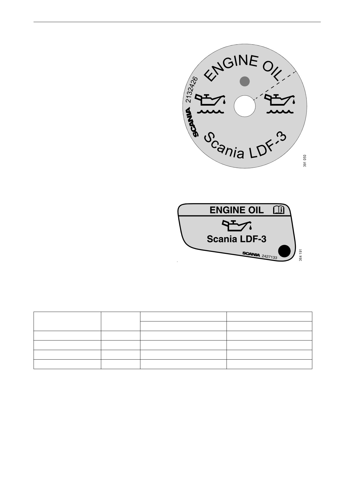
Labels for filled engine oil grade
When changing oil it is important to use the cor-
rect engine oil grade. The oil filler should there-
fore be clearly marked with a label for the filled
oil grade. However, there are only labels for oils
with Scania LDF approval and oil grade
ACEA E7.
Stick on a new label if the oil type or oil grade is
changed in favour of any of the oil types above.
Replace the label if it is missing.
Filling label in the cylinder block.
Filling label in the rocker cover.
If the oil grades below are used, you can order oil
filler labels from Scania.
Oil grade
Colour
Part no.
Part no.
Filling in the cylinder block
Filling in the rocker cover
Scania LDF-3
Red
2 132 426
2 427 133
Scania LDF-2
Blue
2 132 424
-
Scania LDF
Grey
2 269 345
-
ACEA E7
White
2 132 425
2 427 132
28
Lubrication system
Oil analysis
To be able to extend the oil change intervals us-
ing an oil analysis, Scania LDF-3 and LDF-2 oils
must be used. Certain laboratories offer engine
oil analysis.
The following conditions must remain fulfilled
when the oil is changed:
• Viscosity at 100°C (212°F): max. ±20% of
original value of the fresh oil.
• TBN (in accordance with ASTM D4739): >
3.5.
• TBN (in accordance with ASTM D4739): >
TAN (in accordance with ASTM D664).
• Soot (DIN 51452): < 3%.
Such analysis measures the oil's TBN (Total
Base Number), TAN (Total Acid Number), fuel
dilution, water content, viscosity and the quanti-
ty of particles and soot in the oil.
The result of a series of analyses is used as the
basis for establishing a suitable oil change inter-
val.
If the conditions are changed, a new oil analysis
programme must be carried out to establish new
oil change intervals. Work out the new oil
change interval for the engine in conjunction
with the workshop.
REQUIREMENT!
Only Scania LDF oils may be used in conjunc-
tion with oil analysis and a possible extended oil
change interval.
Depending on the market, the warranty condi-
tions may also change if the oil change intervals
differ from the recommended Scania timetable.
29
Lubrication system
Checking the oil level
Note:
2
2
1
Leave the engine off for at least 7 minutes before
you check the oil level.
If the oil level exceeds the maximum level, the
oil must be changed. Check the cause if the oil
level exceeds the maximum level and contact
your nearest Scania workshop if you suspect a
fault.
1. Remove the oil dipstick (1) and check the oil
level. The correct level is between the mini-
mum and maximum marks on the oil dip-
stick.
2. Fill with more oil at point 2 in the illustration
1. Oil dipstick.
when the oil level is at or below the lower
2. Oil filler.
mark.
Information on the correct oil type is found
under the heading Oil grade.
Maximum angles of inclina-
tion during operation
Maximum permissible angles of inclination dur-
30°
ing operation vary, depending on the type of oil
sump. See illustration.
30°
30°
30°
25°
25°
30°
30°
25°
25°
30°
30°
30
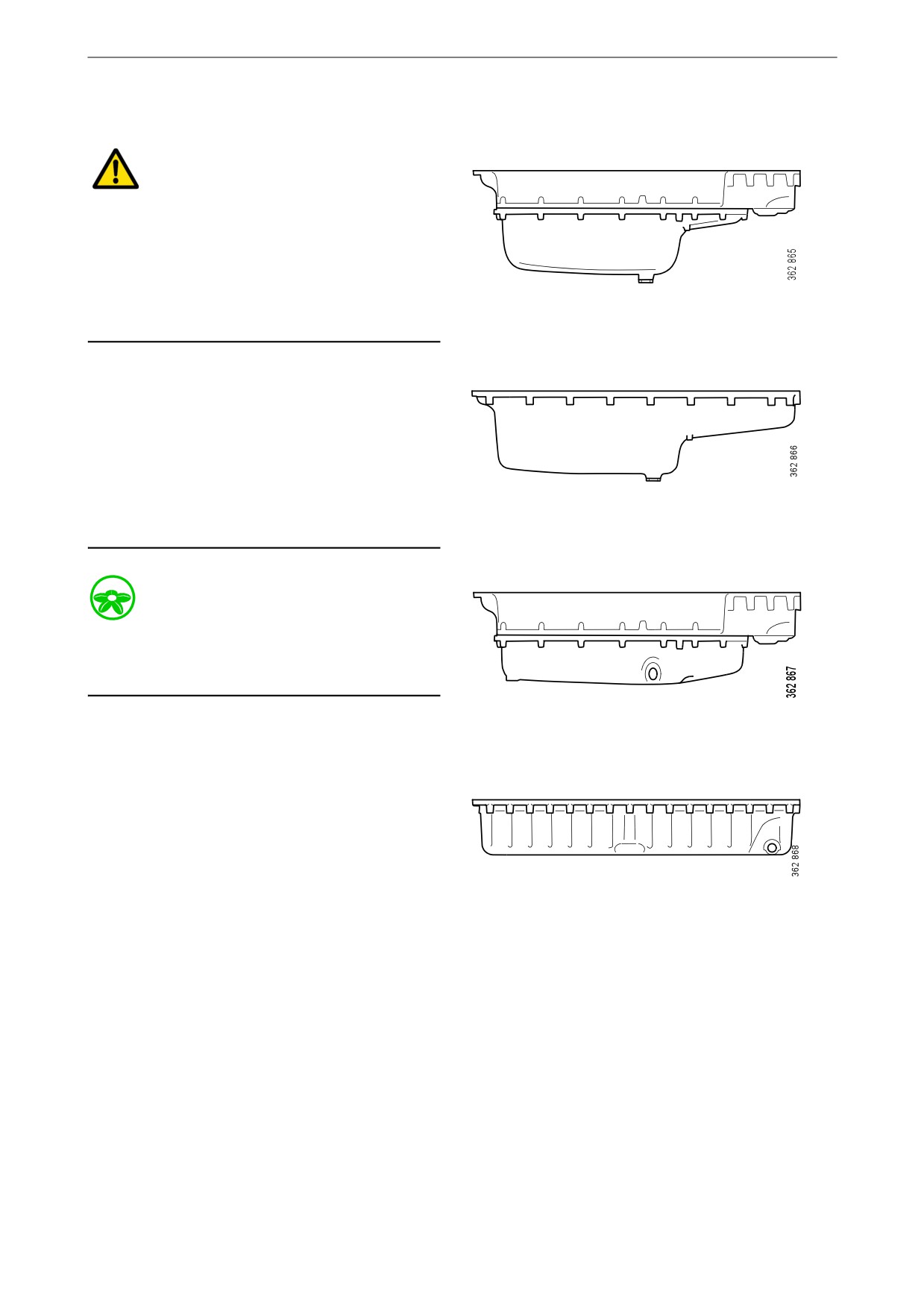
Lubrication system
Changing the oil
WARNING!
Hot oil can cause burns and skin irritation. Wear
protective gloves and eye protection when
changing hot oil. Make sure that there is no pres-
sure in the lubrication system before changing
the oil. The oil filler cap must always be in place
when starting and running the engine to prevent
Max. 45 litres (11.9 US gallons).
oil being ejected.
Min. 39 litres (10.3 US gallons).
Note:
Change oil more often if the engine is subjected
to particularly demanding operation, such as a
dusty environment, or if deposits on the paper in
the centrifugal oil cleaner are thicker than 28 mm
(1.1 in).
Max. 36 litres (9.5 US gallons).
Renew the oil filter and clean the centrifugal oil
cleaner when changing oil.
Min. 30 litres (7.9 US gallons).
Environment
Use a suitable container. Used oil must be dis-
posed of as specified in national and internation-
al laws and regulations.
Max. 34 litres (9.0 US gallons).
Min. 28 litres (7.4 US gallons).
1. Unscrew the oil plug and drain the oil when
the engine is hot. In certain engine types the
oil is pumped out by means of a bilge pump.
If the engine is drained via the valve, the oil
should be hot. Alternatively, use a pump.
This so that draining occurs more quickly.
2. Wipe off the magnet on the oil plug.
Max. 30 litres (7.9 US gallons).
3. Renew the gasket on the oil plug.
Min. 25 litres (6.6 US gallons).
4. Refit the oil plug.
5. Fill with the amount of oil specified for the
oil sump.
6. Wait at least 7 minutes.
7. Check the level on the oil dipstick.
31